
Introduction
A synchronous sequential circuit combines combinational logic with edge-triggered flip-flops sharing a common clock. Its behaviour is a finite state machine (FSM): present state and inputs determine outputs and next state. Mealy machines let outputs depend on inputs and state; Moore machines let outputs depend on state only.
GATE asks you to analyse a given circuit into a state table, design sequence detectors (overlapping or not), count the states and flip-flops a machine needs, reduce a state table, and derive flip-flop input equations.
Prerequisites
- Latches and Flip-Flops: FF characteristics and excitations.
Core concepts
Model
- State register: FFs encode up to states, so states need FFs with binary encoding, or FFs with one-hot encoding.
- Next-state logic: combinational map .
- Output logic: Mealy or Moore .
Design procedure
- Word specification to state diagram (or ASM chart).
- State table; reduce equivalent states if asked.
- Assign binary codes to states.
- Choose FF type; derive excitation inputs from present/next bits.
- Minimize excitation and output Boolean functions; implement.
Sequence detectors
Classic: detect overlapping or non-overlapping patterns such as on a serial input. Each state records the longest prefix of the pattern that is also a suffix of the input seen so far.
- Overlapping: after a match, the machine keeps the longest proper suffix of the pattern that is also a prefix. For , after a match the last bit 1 is kept, so the stream holds two matches (ending at bits 4 and 7).
- Non-overlapping: after a match the machine returns to the start state, and the same stream holds one match.
State counts for a pattern of length . A minimal Mealy detector has states (prefix lengths to ); the output 1 sits on the arc that completes the pattern. A minimal Moore detector has states, because "just matched" must be a state of its own with output 1. For : 4 Mealy states (2 FFs) and 5 Moore states (3 FFs).
Mealy versus Moore
| Mealy | Moore | |
|---|---|---|
| Output depends on | state and input | state only |
| Reaction | can change asynchronously with input (still sampled if registered) | changes on clock with state |
| States | often fewer | often more |
Timing difference. In this detector example, the unregistered Mealy output uses the pre-update state and current input and may assert on the final input symbol; the current-state Moore output appears after the edge entering the matching state. Calling this a one-cycle shift depends on the sampling convention. Equivalent Mealy/Moore realizations do not have a universal one-clock lag from their definitions alone.
How it works
Analysis
From a schematic: write FF excitation equations, apply characteristics to get next-state maps, build the state table, draw the diagram. With D flip-flops the next state equals the D inputs; with JK or T, substitute into or first.
State reduction
Two states are equivalent if they produce the same output sequences for every input sequence. Equivalent states can be merged without changing the behaviour seen from outside.
Partition refinement. Start with blocks of states that have the same output row. Repeatedly split a block when two of its states move, on some input, to different blocks. Stop when nothing splits; each block is one state of the minimal machine. Identical rows (same outputs and same next states) are only the easy case: two states can be equivalent even when their next states differ, as long as those next states are themselves equivalent. The implication-chart method finds the same result.
State assignment
Binary encoding uses the fewest FFs. Gray-adjacent codes for states that transition into each other can reduce logic and avoid some simultaneous bit flips. One-hot encoding uses one FF per state: the next-state logic is simple, but the FF count equals the state count. Unused codes (for example 1 of 4 codes when 3 states use 2 FFs) may be treated as don't-cares in the excitation maps, or given a transition back into the used states so that the machine cannot stay stuck there after a glitch.
Algorithms and pseudocode
Arrays and states are 0-indexed; <- is assignment.
SEQ-DESIGN(diagram, FFtype)
1  table <- state table from diagram
2  assign binary codes to states
3  for each FF bit
4      derive required Q+ from codes
5      set excitation from excitation table of FFtype
6  minimize excitation and output functions
7  return gate network plus FF bank

REDUCE(states, inputs, next, out)          // partition refinement
1  block[s] <- class of the output row out[s][.] for every s
2  repeat
3      key[s] <- (block[s], block[next[s][x]] for every input x)
4      newblock[s] <- class of key[s]
5      changed <- (number of classes grew)
6      block <- newblock
7  until not changed
8  return block                            // one state per class

DETECTOR-NEXT(pattern P, k, bit b)         // overlapping, Mealy
1  w <- P[0..k-1] followed by b
2  if w = P then output 1 and use w <- w without its first symbol
3  return length of the longest suffix of w that is a prefix of P
REDUCE does work per round with hashing, for states.
- Best case: 1 round. This happens when the first refinement adds no class, for example when the output rows already separate every state, or when all states have the same output rows (then all of them are equivalent).
- At most rounds for , hence overall. For , a chain attains : input 1 advances state to (last stays put), input 0 stays put, and only the last state outputs 1 on input 1. Each round splits off another state; the final no-change check is included.
- There is no useful average case; it depends on the machine. For a non-overlapping detector, line 2 of DETECTOR-NEXT returns state 0 instead.
Mathematical explanation
A deterministic FSM is with output function either (Moore) or (Mealy). Encoding injects into , so . Related TOC view: Deterministic Finite Automata omits binary encoding and gates.
Why the Mealy detector needs exactly states. The prefix states are pairwise distinguishable. For , feed the bits . From state the last of them completes a match. From state the matched prefix can reach at most , so there is no match. Fewer than states would merge two of them.
Worked examples
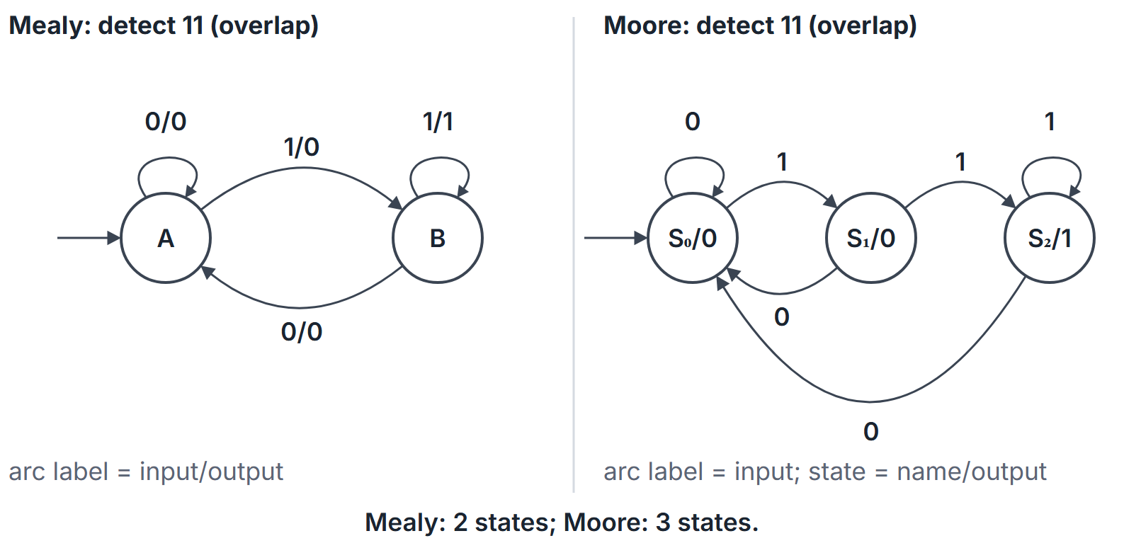
Example 1: detect (Mealy, overlap)
States (no progress), (last bit 1). From : input 0 to out 0; input 1 to out 0. From : input 1 to out 1; input 0 to out 0.
The Moore version needs three states: with output 0 (no progress), with output 0 (last bit 1), with output 1 (last two bits 11). Input 1 moves ; input 0 returns every state to . During the four cycles of input , the Mealy output is . The Moore output (the label of the present state) is and stays 1 in the fifth cycle: the same response one cycle later.
Example 2: Moore 11 detector with D flip-flops
Encode , , as ; code 11 is unused (don't-care). Next state: input gives 00 from every state; gives from and from and . Using the don't-cares,
Neither equation can shrink: has a single on-set row (001), and the don't-cares 110 and 111 are not adjacent to it.
Example 3: analysis of a D flip-flop circuit
, , output . Evaluating every row:
| Next, | Next, | , | , | |
|---|---|---|---|---|
| 00 | 00 | 01 | 0 | 0 |
| 01 | 00 | 11 | 1 | 0 |
| 10 | 00 | 10 | 1 | 0 |
| 11 | 00 | 10 | 1 | 0 |
The rows for 10 and 11 are identical, so those two states merge. After that merge, state 01 also matches: it goes to 00 on and to 11, now the same state as 10, on , with the same outputs. The minimal machine has only two states: 00 (last input 0, or reset) and (last input 1), with exactly on a 1 followed by 0. Stopping after the first merge, at three states, is the usual mistake. It is a Mealy machine because depends on .
Example 4: reduction that needs refinement
| State | Next, | Next, | Out, | Out, |
|---|---|---|---|---|
| A | A | B | 0 | 0 |
| B | C | B | 0 | 0 |
| C | A | D | 0 | 1 |
| D | E | D | 0 | 0 |
| E | A | B | 0 | 1 |
By outputs: and . Refining: on , goes to (first block) while and go to and (second block), so splits off. Now : and go to and to ; and go to and to . Nothing splits, so the minimal machine has 3 states, even though no two rows of the original table are identical. The input separates from : outputs , outputs .
Example 5: overlapping and non-overlapping
Mealy states to hold the matched prefix length.
| State | ||
|---|---|---|
| /0 | /0 | |
| /0 | /0 | |
| /0 | /0 | |
| /0 | /1 |
on 1 stays in (the input still ends in ). The overlapping detector goes from on 1 to , keeping the final 1; the non-overlapping one goes to . On , the outputs are (overlapping) and (non-overlapping).
Example 6: overlapping detector for
States: (start), (got 1), (got 10). Mealy outputs 1 on the transition that completes . From , input 1 goes to (the last 1 begins a new pattern); from , input 0 goes to ; from , input 1 stays in . On the output is .
Example 7: unused states
With 3 states in 2 FFs, one code is unused; treat as don't-care next state or force a recovery transition as the question requires.
Important properties and observations
- All FFs share one clock in the synchronous model; no ripple between state bits for the state register (counters may still ripple; see Registers and Counters).
- Self-loops and overlapping detections are common pitfalls in diagrams.
- Output glitches in Mealy machines: if outputs feed asynchronous logic, prefer registered Moore outputs.
- Flip-flop count: binary, one-hot; 5 states need 3 FFs binary.
Common misconceptions.
- "Mealy always uses fewer states." Often, not always; for detectors it saves exactly one.
- "Next state depends only on input." It depends on present state too.
- "Only identical rows can be merged." Partition refinement merges states whose next states are equivalent, not identical.
- "The Moore and Mealy outputs rise in the same cycle." For the shown pre-edge Mealy/current-state Moore convention, assertion occurs on opposite sides of the state-update edge; whether this is an extra cycle depends on sampling, not the definitions alone.
GATE examination perspective
- DRAW THE DIAGRAM. Label transitions as (Mealy) or inputs on arcs and outputs in bubbles (Moore).
- STATE AND FF COUNTS. Length- detector: Mealy, Moore states; FFs .
- EXCITATION MAPS. From state codes to D/T/JK inputs, with unused codes as don't-cares.
- OVERLAP. For sequence , decide whether overlapping is required.
- REDUCTION. Partition by outputs, then refine by next-state blocks.
- UNUSED STATES. Don't-cares versus safe recovery.
Summary
Sources
- M. Morris Mano, M. D. Ciletti, Digital Design, 5th ed., Pearson, 2013: Chapter 5, Sections 5.5, 5.7 and 5.8 (analysis of clocked sequential circuits; state reduction and assignment; design procedure).