
Introduction
Adders are the core combinational blocks of arithmetic. A half adder adds two bits; a full adder adds three bits (two operands and a carry-in). Chaining full adders yields a ripple-carry adder (RCA); carry-lookahead (CLA) computes the carries in parallel to cut the delay. Two's-complement subtraction is addition of the bitwise complement with carry-in 1, so one circuit with a mode line both adds and subtracts.
GATE asks for gate-level equations, gate and delay counts under a stated gate model, carry-lookahead expressions, and the overflow and carry flags of a result.
Prerequisites
- Combinational Circuit Design: truth tables to gates, critical path.
- Signed Number Representation: two's complement and overflow.
Core concepts
Half adder
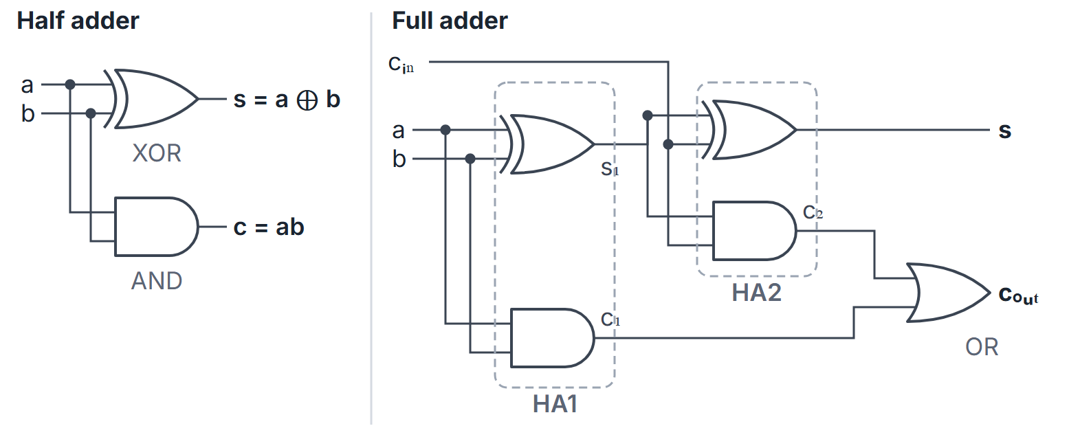
Inputs ; outputs , . One XOR and one AND.
Full adder
Inputs ; outputs
Equivalently with generate and propagate .
| 0 | 0 | 0 | 0 | 0 |
|---|---|---|---|---|
| 0 | 0 | 1 | 0 | 1 |
| 0 | 1 | 0 | 0 | 1 |
| 0 | 1 | 1 | 1 | 0 |
| 1 | 0 | 0 | 0 | 1 |
| 1 | 0 | 1 | 1 | 0 |
| 1 | 1 | 0 | 1 | 0 |
| 1 | 1 | 1 | 1 | 1 |
is the odd-parity function and the majority function of the three inputs; the pair is the 2-bit binary count of 1s among .
Two half adders and an OR. The first half adder gives and ; the second adds : and carry . Then . The OR never sees two 1s, because forces . Totals: 2 XOR, 2 AND, 1 OR. A full adder can also be built from 9 two-input NAND gates (the 4-NAND XOR used twice, with the shared NANDs reused for the carry).
Half and full subtractor
A full subtractor computes : difference (the same as the sum) and borrow out
The borrow is the full-adder carry with complemented. The half subtractor is , .
Ripple-carry adder
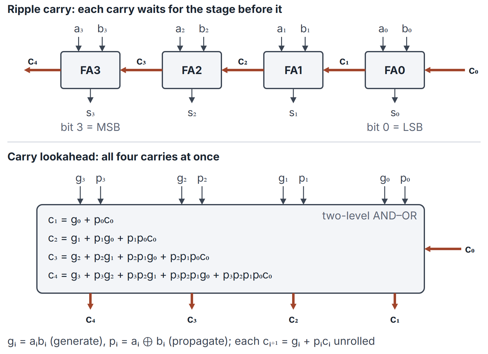
full adders; for addition; the carry out of stage is the carry into stage . Worst-case delay grows as because the carry must pass through every stage: adding propagates a carry from bit 0 to bit .
Carry-lookahead
Define , (XOR form). Then . Unrolling for a 4-bit block:
Every carry is a two-level AND-OR of the , and , so all four are available at the same time. The cost is fan-in: needs a 5-input AND and a 5-input OR. For a 4-bit block the lookahead unit uses AND gates and 4 OR gates.
Group generate and propagate. A 4-bit block also outputs
so that . means the block creates a carry by itself; means it passes an incoming carry through. A second-level lookahead unit combines block pairs with the same equations, giving delay for bits.
Adder-subtractor
Two's-complement subtract : feed to the adder and set . With a mode line (0 add, 1 subtract), each adder input is and . The signed overflow flag is ; the carry flag is , and in subtraction signals an unsigned borrow ().
How it works
Delay model
Gate-delay convention used in this note. Every two-input or multi-input AND, OR and XOR gate costs 1 unit; inputs arrive at time 0. Other delay models are also used (for example 2 units per carry stage); always rebuild the count from the model in the stem.
Ripple-carry. and are ready at 1. Stage computes with an AND then an OR, so the carry advances 2 units per stage after the first: at 3, at 5, and in general
with at 2. For : at 8 and at 9. For : at 32 and at 33.
Carry-lookahead, 4 bits. at 1, every carry to at 3 (one AND level, one OR level), every sum at 4. The delay does not grow with the bit position inside the block.
16 bits from four 4-bit CLA blocks, carries rippling between blocks. Inside each block is ready at 3 and at 2. The block carry-outs are at 4, at 6, at 8 and at 10 (2 units per block). The last block computes from at 10, so is ready at 11. Compare 32 for the 16-bit ripple adder.
Overflow
For signed two's complement, overflow (carry into sign XOR carry out of sign), as in Signed Number Representation.
Algorithms and pseudocode
Arrays are 0-indexed from the LSB; <- is assignment.
FULL-ADDER(a, b, cin)
1  s <- a XOR b XOR cin
2  cout <- (a AND b) OR (b AND cin) OR (a AND cin)
3  return (s, cout)

RIPPLE-ADD(A[0..n-1], B[0..n-1], c0)
1  c <- c0
2  for i <- 0 to n-1
3      (S[i], c) <- FULL-ADDER(A[i], B[i], c)
4  return (S, c)

CLA-CARRIES(g[0..n-1], p[0..n-1], c0)
1  c[0] <- c0
2  for i <- 0 to n-1
3      c[i+1] <- g[i] OR (p[i] AND c[i])   // hardware unrolls this
4  return c

ADD-SUB(A, B, M, n)                       // M = 0 add, M = 1 subtract
1  for i <- 0 to n-1: B'[i] <- B[i] XOR M
2  (S, cn) <- RIPPLE-ADD(A, B', M)
3  V <- (NOT (A[n-1] XOR B'[n-1])) AND (A[n-1] XOR S[n-1])
4  return (S, cn, V)
RIPPLE-ADD uses full adders and delay. A one-level CLA over bits uses AND gates of fan-in up to for constant delay; a tree of 4-bit lookahead units uses gates and delay.
Mathematical explanation
Unrolling gives
with the convention . In words: there is a carry into position exactly when some position generates one and every position between and propagates it.
Propagate variants. Some texts use (OR) for the carry chain. The carry equation still holds, because the two definitions differ only when , and then already. The sum, however, needs the XOR form: , not .
Subtraction correctness. , which is modulo . The extra is the carry out: it is 1 exactly when as unsigned numbers.
Array multiplier sizing. A combinational multiplier for a -bit multiplier and -bit multiplicand forms partial-product bits with AND gates and adds them with adders of bits each, producing a -bit product. For multiplicand bits and multiplier bits: 12 AND gates, two 4-bit adders, a 7-bit product ().
Worked examples
Example 1: full-adder truth
For : , (total 3).
Example 2: 4-bit RCA
From the LSB: bit 0 gives , carry 0; bit 1 gives , carry 0; bit 2 gives , carry 1; bit 3 gives , carry 0. The pattern is , which is 11 unsigned and correct; as signed 4-bit it is , and flags the overflow of .
Example 3: subtract and as additions
- , , , : . The result is with carry out 1 (no borrow).
- , , : . The result is with carry out 0, the unsigned borrow; because is in range.
Example 4: lookahead values
For , , : and (bit 3 on the left). Then ; ; ; . Sums give with : . Group signals: and .
Example 5: delay comparison
With the 1-unit gate model above, a 16-bit RCA needs 33 units for and 32 for . Four 4-bit CLA blocks with rippling block carries give at 11. A single 16-bit two-level lookahead would be faster still (all carries at 3) but needs a 17-input AND and OR for , which is why hierarchical lookahead is used. Answers claiming "CLA is always two gate delays for any " ignore fan-in.
Example 6: BCD digit add
Add 4-bit BCD digits as binary. If the sum exceeds 9 or the 4-bit addition carries out, add and produce a decimal carry. Example: (11); adding gives : digit 1 with a decimal carry, that is . Details are in the Binary Codes note.
Important properties and observations
- The full-adder carry is the majority function and its sum is three-input parity; in the two-half-adder build, the final OR can be an XOR.
- Propagate definition variants: serves the carry chain; only also gives the sum.
- Serial adder: one full adder plus a carry flip-flop, one bit per clock, cycles for bits; sequential, see the Registers and Counters note.
- BCD adder: binary add then correction when the digit sum exceeds 9.
- Incrementer: an adder with and reduces to a chain of half adders.
Common misconceptions.
- "Carry-lookahead eliminates all delay dependence on ." Only inside limited fan-in; asymptotically with trees.
- "Overflow bit is ." That is unsigned carry; signed overflow needs .
- "In subtraction a carry out means something went wrong." With , carry out 1 means no borrow ( unsigned).
- "The full subtractor borrow equals the full adder carry." It is the carry with complemented.
- "Delay is the same in every model." Stage delays of 2 per bit, or XOR counted as 2 levels, change every number; follow the stem.
GATE examination perspective
- WRITE AND . Memorise XOR and majority forms, and the borrow form for subtractors.
- RCA VS CLA DELAY. Linear versus lookahead; rebuild arrival times from the stated gate delays and fan-in.
- UNROLL A CARRY. Expand or in ; count its AND gates and their fan-in.
- BLOCK CLA. Group and ; rippling between blocks costs 2 levels per block in the 1-unit model.
- SUBTRACT CONTROL. XOR with on and tie to .
- FLAGS. ; ; in subtraction means borrow.
- MULTIPLIER SIZE. ANDs, adders of bits, product bits.
Summary
Sources
- M. Morris Mano, M. D. Ciletti, Digital Design, 5th ed., Pearson, 2013: Chapter 4, Sections 4.5 (binary adder-subtractor, including carry propagation and lookahead), 4.6 (decimal adder) and 4.7 (binary multiplier).