
Introduction
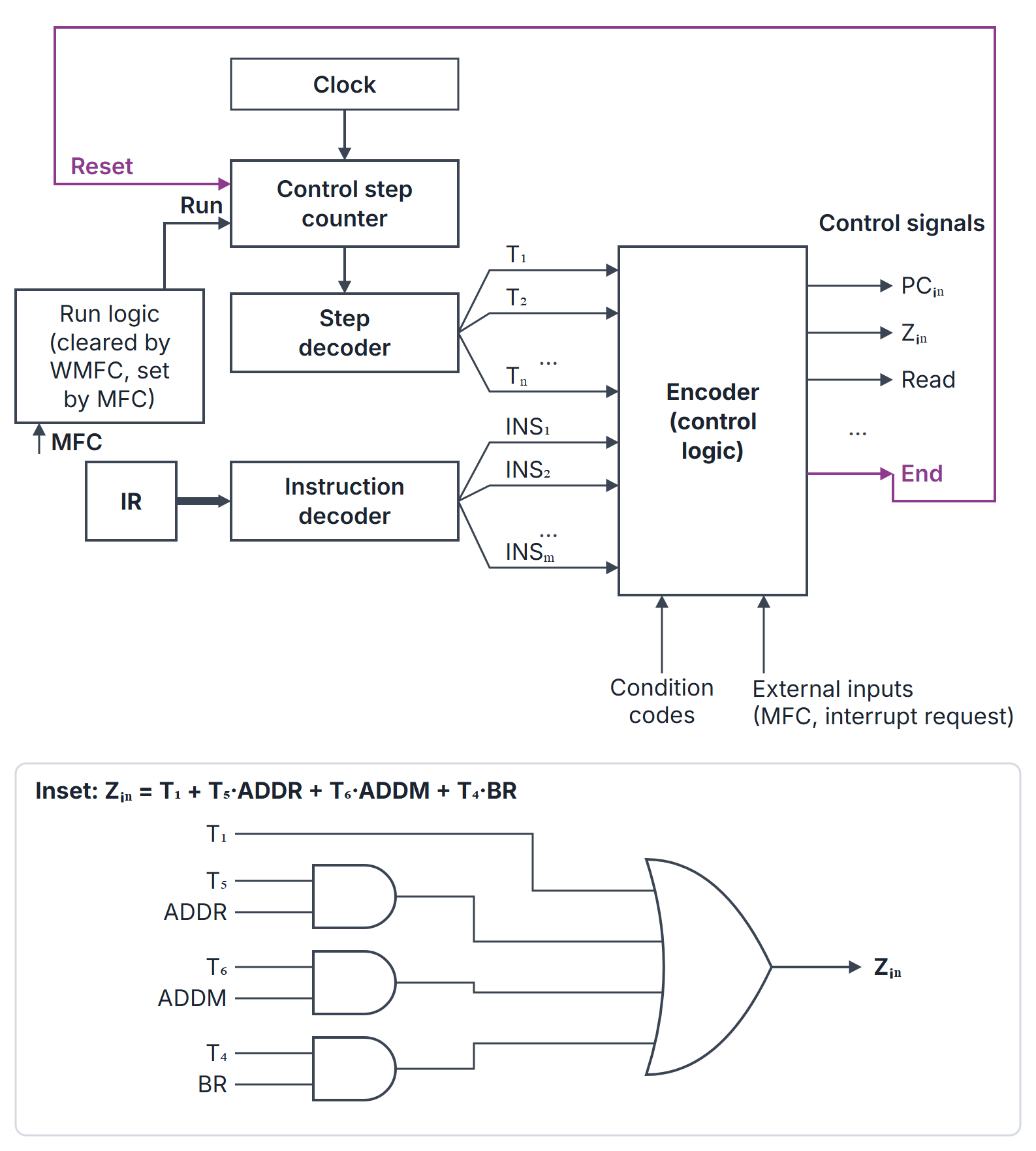
A hardwired control unit generates the processor's control signals with fixed combinational logic driven by a step counter. For each instruction, the datapath needs a particular set of signals in step 1, another in step 2, and so on (the control sequence); a hardwired unit turns those tables into logic equations of the form "signal = OR of (step AND instruction AND condition)" and builds them directly in gates. It is in effect a finite state machine whose states are the control steps.
GATE asks you to write the logic expression for a control signal from given control sequences, to size the step counter and decoders, to count the flip-flops a control FSM needs, and to compare hardwired with microprogrammed control. The control sequences themselves come from CPU Datapath and Instruction Cycle.
Prerequisites
- CPU Datapath and Instruction Cycle: the control steps and signals of each instruction.
- Sequential Circuit Design and Finite State Machines: counters, state encoding and next-state logic.
Core concepts
Building blocks
| Block | Input | Output |
|---|---|---|
| Control step counter | Clock; Reset (from End); Run (held at 0 during WMFC) | Step number in binary |
| Step decoder | Counter value ( bits) | One-hot step lines |
| Instruction decoder | Opcode field of IR | One line per instruction (ADD, BR, ...) |
| Encoder (control logic) | Step lines, instruction lines, condition codes, external inputs (MFC, interrupt request) | Every control signal |
The counter advances one step per clock. The signal End resets it to step 1, starting the next fetch. While the processor waits for memory, Run is 0 and the counter holds its value; MFC sets Run again.
Control signal equations
A signal is active in step for instruction if the control sequence of lists in step . Fetch steps are the same for every instruction, so they appear without an instruction term:
This is a sum of products: an AND gate per term and one OR gate per signal.
As a finite state machine
Each (instruction, step) pair is a state. With states, binary encoding needs flip-flops and next-state logic; one-hot encoding needs flip-flops but almost no decoding. The step-counter design above is a compact encoding where the state is (opcode in IR, step count).
Hardwired against microprogrammed
| Aspect | Hardwired | Microprogrammed |
|---|---|---|
| Signal generation | Logic gates | Words read from a control memory |
| Speed | Faster (gate delays only) | Slower (control memory access each step) |
| Changing the instruction set | Redesign the logic | Rewrite the microprogram |
| Complexity for large ISAs | Grows quickly, irregular | Regular, easier to design and debug |
| Typical use | RISC processors | CISC processors, emulation |
How it works
Worked derivation
Using the single-bus control sequences of CPU Datapath and Instruction Cycle:
| Step | Fetch (all instructions) | ADD R1, R2, R3 (ADDR) | ADD R1, (R3) (ADDM) | BR offset (BR) |
|---|---|---|---|---|
| 1 | PC, MAR, Read, Select4, Add, Z | |||
| 2 | Z, PC, Y, WMFC | |||
| 3 | MDR, IR | |||
| 4 | R2, Y | R3, MAR, Read | Offset, SelectY, Add, Z | |
| 5 | R3, SelectY, Add, Z | R1, Y, WMFC | Z, PC, End | |
| 6 | Z, R1, End | MDR, SelectY, Add, Z | ||
| 7 | Z, R1, End |
For BR, Y still holds the updated PC from step 2, so step 4 adds the offset field of IR to it. Reading down the columns:
Conditional branch. For BRN (branch if negative), step 4 is the same as for BR plus End when , and step 5 runs only when . Then End gains the terms , and gains .
Algorithms and pseudocode
DERIVE-EQUATIONS(sequences)            // sequences[I][i] = set of signals in step i of I
  for each signal X
      terms <- empty
      for each fetch step i with X in fetch[i]
          add "T_i" to terms
      for each instruction I, step i with X in sequences[I][i]
          add "T_i AND I" to terms       // add the condition factor if the step is conditional
X <- OR of termsCONTROL-CYCLE() // hardware behaviour every clock edge
if End then counter <- 0
else if Run then counter <- counter + 1
T_lines <- decode step label T_(counter + 1) from counter; I_lines <- decode(IR.opcode)
every control signal <- its equation(T_lines, I_lines, flags, MFC, IRQ)Mathematical explanation
Counter and decoder size. Encode step label by stored counter value ; labels are not literal stored values. Reset to 0 and decode . If the longest control sequence has steps, the counter needs bits and the step decoder is -to-, of which outputs are used. An opcode of bits gives a -to- instruction decoder.
FSM flip-flops. A control FSM with states needs at least flip-flops; one-hot uses .
Gate count of one signal. A signal with product terms needs AND gates (fewer where a term is a lone ) and one -input OR gate.
Worked examples
Example 1: sizing
A processor's longest control sequence has 12 steps and the opcode is 6 bits. Counter: bits; step decoder 4-to-16 with 12 outputs used; instruction decoder 6-to-64.
Example 2: reading an equation
From the table above, is active in four (step, instruction) situations: step 1 of every instruction, step 5 of ADDR, step 6 of ADDM and step 4 of BR. During ADDM, is therefore active in steps 1 and 6 only. needs three 2-input AND gates (the term needs none) and one 4-input OR gate.
Example 3: FSM states
A control unit is designed as an FSM with 3 fetch states shared by all instructions, and execute states of 3, 4, 2 and 2 steps for four instructions: states. Binary encoding: flip-flops; one-hot: 14. If the execute states of different instructions are merged by step number (a step counter plus the opcode in IR), the counter needs only bits for at most steps.
Example 4: conditional branch timing
BRN takes 4 steps when not taken (End in step 4) and 5 when taken. With 30% of BRN taken, the average is steps.
Important properties and observations
- One equation per control signal, a sum of (step AND instruction AND condition) terms.
- Fetch steps contribute bare terms, since every instruction shares them.
- End resets the counter; Run freezes it during memory waits.
- Condition codes enter as extra AND factors, so a conditional instruction can end early.
- Hardwired control is fast but rigid: a new instruction means new logic.
- The control unit is an FSM; a step counter is a compact state encoding.
- Common misconceptions.
- "Hardwired control cannot handle variable-length sequences." End can occur in any step.
- "Microprogrammed control is faster because it is programmable." It is slower; a control memory read is added to each step.
- "The counter must count to the number of instructions." It counts steps of the longest sequence.
GATE examination perspective
- SIGNAL EQUATION. Scan every column of the control-sequence table for the signal; OR the (step AND instruction) terms.
- COUNTER SIZE. bits with zero-based stored step encoding.
- FLIP-FLOPS. binary, one-hot.
- CONDITIONAL INSTRUCTIONS. Add the flag as an AND factor; count steps for both outcomes.
- COMPARISON. Hardwired: fast, RISC, hard to change. Microprogrammed: flexible, CISC, slower.
- AVERAGE STEPS. Weight each path by its probability.
Summary
Sources
- C. Hamacher, Z. Vranesic, S. Zaky, Computer Organization, 5th ed., McGraw-Hill, 2002: Chapter 7, Sections 7.2 (Execution of a Complete Instruction, including 7.2.1 Branch Instructions) and 7.4 (Hardwired Control, including 7.4.1 A Complete Processor).
- D. A. Patterson, J. L. Hennessy, Computer Organization and Design: The Hardware/Software Interface, 5th ed. (MIPS edition), Morgan Kaufmann, 2013: Appendix D, Sections D.2 (Implementing Combinational Control Units) and D.3 (Implementing Finite-State Machine Control).
- W. Stallings, Computer Organization and Architecture, 10th ed., Pearson: Sections 20.2 (Control of the Processor) and 20.3 (Hardwired Implementation).