
Introduction
A register is a bank of flip-flops sharing a clock, often with load, clear and shift controls. A counter is a register whose state sequence follows a counted order.
GATE asks for the state sequence and modulus of a given counter circuit (for example a shift register with feedback), ripple versus synchronous designs and their maximum clock rates, ring and Johnson counters with their unused states, mod- counters by reset or load, and shift-register contents after a number of clocks.
Prerequisites
Core concepts
Registers
- Parallel-load register: equals either the external input (when ) or (hold), selected by a 2:1 MUX in front of each flip-flop.
- Shift register: serial-in serial-out (SISO), serial-in parallel-out (SIPO), parallel-in serial-out (PISO), universal (bidirectional with mode controls). Loading bits serially takes clocks; an -bit SISO register delays its input by clocks.
- Shift left by one multiplies an unsigned binary integer by 2 (if no overflow out of MSB); shift right divides by 2 (floor).
Binary counters
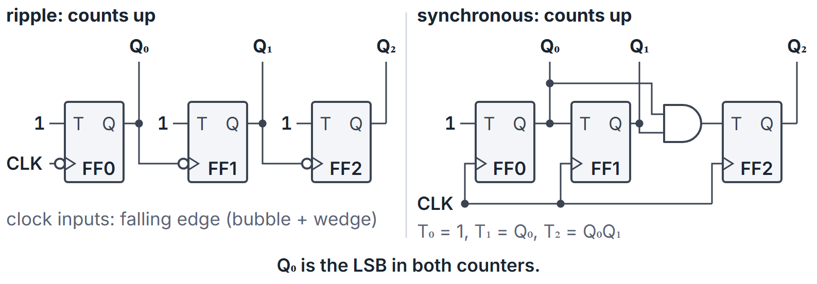
- Ripple (asynchronous): FF0 toggles every clock; FF clocks from the previous FF's output. With falling-edge flip-flops, clocking from counts up; clocking from counts down. With rising-edge flip-flops the two are swapped. Simple, but cumulative delays skew the bits; decoding glitches possible.
- Synchronous: all FFs share the clock; combinational logic feeds T or JK toggles when lower bits are 1 (for up-count).
Modulus
A counter with distinct states in cycle has modulus . An -FF binary counter naturally has modulus ; forcing a reset/load at a chosen code yields a smaller modulus (for example mod-6, mod-10 BCD). A mod- counter needs at least flip-flops.
Ring and Johnson
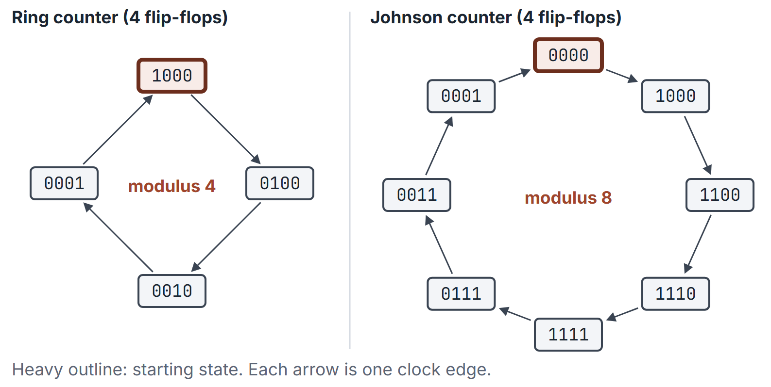
- Ring: FFs, one circulating hot 1; modulus . Needs a valid one-hot reset. It uses of the patterns, leaving unused; the all-zero state maps to itself, so a ring counter that loses its 1 stays at .
- Johnson (twisted ring): shift with complement of last FF fed to first; the intended cycle has modulus . Valid states fill zeros with ones and then empty them. For , the unused patterns form separate cycles, so the bare counter is not self-starting. For , there are no unused states. For , the 8 unused patterns form a second 8-state cycle unless recovery logic steers them back.
- Each Johnson state can be decoded with one 2-input AND gate, because exactly one bit changes per step, including the wrap-around.
How it works
Synchronous up-counter T inputs
; for . Down-count uses complemented conditions: . An up/down counter with control uses .
Ripple transients
In an up ripple counter the bits change one after another. Going from to , falls first, which clocks , and so on. The outputs pass through , and before reaching . A decoder on the outputs can glitch on those transient codes.
Speed limits
- Ripple: if every bit must be settled before the next clock edge (for example to decode the count), (plus any decoder delay).
- Synchronous: with parallel AND gates for the , independent of until fan-in limits force an AND chain.
Truncated sequence
Detect the unwanted state (for example 1010 for decade after 1001) and asynchronously clear, or synchronously load 0000 on the next clock. With an asynchronous clear the unwanted state appears briefly, for the clear-path delay, before the reset. Synchronous clear is preferred to avoid short glitch states. With synchronous load, the detector watches the last wanted state (1001), not the first unwanted one.
Analysing a counter circuit
Write each flip-flop's next state from its inputs, then step from the reset state until a state repeats; the cycle length is the modulus. Then check every unused state: if each one reaches the main cycle, the counter is self-starting; if some unused states cycle among themselves, it can lock out.
Universal shift-register mode table
A typical 4-bit universal shift register uses two mode bits :
| Action | |
|---|---|
| 00 | Hold |
| 01 | Shift right (serial into MSB) |
| 10 | Shift left (serial into LSB) |
| 11 | Parallel load |
Draw the 4:1 MUX in front of each with those four sources. If a figure omits a mode, recover it from the MUX wiring.
Synchronous decade counter
States to then back to . Toggle enables follow binary up-count until the detect of , which synchronously loads zero. Asynchronous clear on is a common textbook alternative; it briefly produces for a hazard window, so synchronous designs are preferred in questions that mention glitch-free decimal outputs.
Algorithms and pseudocode
Arrays are 0-indexed; <- is assignment.
SYNC-UP-NEXT(Q[0..n-1])
1  T[0] <- 1
2  for i <- 1 to n-1
3      T[i] <- AND of Q[0..i-1]
4  for i <- 0 to n-1
5      Q[i] <- Q[i] XOR T[i]
6  return Q

JOHNSON-NEXT(Q[0..n-1])
1  nin <- NOT Q[n-1]
2  for i <- n-1 downto 1
3      Q[i] <- Q[i-1]
4  Q[0] <- nin
5  return Q

MODULUS-AND-SELF-START(next, s0, all_states)
1  seen <- [s0]; s <- next(s0)
2  while s not in seen: append s to seen; s <- next(s)
3  cycle <- seen from the first occurrence of s
4  for each u in all_states not in cycle
5      walk u, next(u), ... for at most |all_states| steps
6      if the walk never enters cycle then return (|cycle|, not self-starting)
7  return (|cycle|, self-starting)
The analysis visits each of the states at most times, steps, trivial for exam sizes.
Mathematical explanation
Counters are cyclic FSMs. Binary counting implements in the state encoding. Bit toggles exactly when bits to are all 1, which is when adding 1 carries into position ; this is the synchronous . It also means bit has period clocks.
Johnson codes are of the possible patterns, and successive codes differ in exactly one bit, including the step from the last back to the first. For , unused patterns exist and cannot reach the valid cycle on their own, because the Johnson next-state map is a bijection: each pattern has exactly one predecessor, so the state graph is a set of disjoint cycles.
Worked examples
Example 1: mod-8 sequence
Example 2: Johnson
(six states). The two unused patterns, and , map to each other: .
Example 3: mod-6 with sync clear
Count ; when state is 5, next load 0. Natural 3-FF codes use 000..101; 110 and 111 unused (lock detection may force reset). With an asynchronous clear instead, the detector is driving an active-low clear: state 110 appears for the clear delay and then becomes 000.
Example 4: ripple delay
If each FF has , a 4-bit ripple needs up to after the clock before all bits settle, so the clock must not exceed if the count is decoded every cycle. A synchronous 4-bit counter with , a 2 ns AND and ns runs at .
Example 5: a shift register with feedback
Three D flip-flops form a shift register , , with . From (written ) the states are : modulus 5. The unused states , and go , and , all into the main cycle, so the counter is self-starting.
Example 6: shift-register contents
A 4-bit shift-right register holds (MSB on the left) with serial input 0. After two clocks it holds ; after four clocks, . Feeding the serial output back to the input instead (a rotate) returns after four clocks.
Example 7: Johnson lock-out
The valid cycle is . Starting from the unused : , a second cycle of 8 that never meets the valid one.
Important properties and observations
- Frequency at FF of a binary counter is .
- BCD decade counter: modulus 10; outputs weight 8421.
- Universal shift register control words select hold, shift L/R, or parallel load.
- Unused-state counts: ring , Johnson ; a 4-bit ring leaves 12, a 4-bit Johnson leaves 8.
- A Johnson counter with FFs divides the clock by at any single output.
Common misconceptions.
- "Ring counter modulus is ." That is Johnson; ring is .
- "Ripple is always slower to the MSB only." Intermediate decoding also glitches.
- "Unused states cannot occur." Power-up can enter them; design recovery.
- "Johnson counters are self-correcting for every size." For n at least 3, unused states form separate cycles and the plain design locks out. For n=1 or 2, all states belong to the intended cycle.
- "Clocking each stage from always counts up." That depends on the active edge.
GATE examination perspective
- MODULUS. Count distinct cyclic states, not number of FFs alone.
- NEXT STATE. Given a figure, compute the following state; step until a state repeats.
- SELF-STARTING. Trace every unused state.
- RING VS JOHNSON. vs ; unused vs .
- RIPPLE VS SYNC. versus ; transient codes in ripple counters.
- EDGE AND DIRECTION. Falling-edge FFs clocked by count up.
Summary
Sources
- M. Morris Mano, M. D. Ciletti, Digital Design, 5th ed., Pearson, 2013: Chapter 6, Sections 6.1 to 6.5 (registers, shift registers, ripple counters, synchronous counters, other counters).