
Introduction
Latches and flip-flops are bistable memory elements. A latch is level-sensitive: while the enable is asserted it follows the input. A flip-flop is edge-triggered: it samples on a clock edge. Characteristic tables say what the next state is; excitation tables say what inputs are needed to force a desired transition.
GATE tests SR latch behaviour (including the forbidden input), the characteristic and excitation tables, conversions between flip-flop types, the race-around condition, sequences of states under given inputs, and setup, hold and maximum clock frequency.
Prerequisites
- Combinational Circuit Design: gates, timing delay.
Core concepts
SR latch (NOR or NAND)
Cross-coupled NOR: , .
| NOR latch result | ||
|---|---|---|
| 0 | 0 | hold |
| 0 | 1 | reset, |
| 1 | 0 | set, |
| 1 | 1 | forbidden: |
With both outputs are 0, so they are no longer complements. If both inputs then return to 0 together, the final state depends on which gate is faster (a race). Under the constraint , the characteristic equation is .
The cross-coupled NAND latch has active-low inputs : holds, sets , resets , and is forbidden, driving both outputs to 1.
Gated (enable) latch
AND (or NAND) gates qualify or with enable. Transparent when enable (for active-high).
D latch
input with , . No forbidden combination; follows while enabled and holds the last value when the enable drops.
Edge-triggered flip-flops
Built from master-slave latches or pulse-triggered designs so the output changes only on the active clock edge (rising or falling). Types:
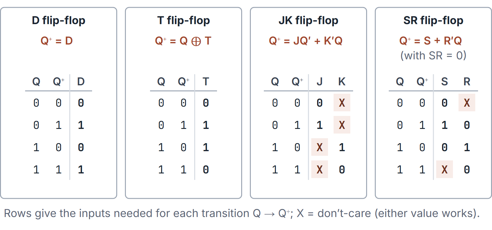
| Type | Characteristic | Excitation (to get ) |
|---|---|---|
| D | ||
| T | ||
| JK | see table below | |
| SR (FF) | like latch; forbid | to set, to reset |
JK excitation.
| 0 | 0 | 0 | X |
|---|---|---|---|
| 0 | 1 | 1 | X |
| 1 | 0 | X | 1 |
| 1 | 1 | X | 0 |
SR and T excitation.
| 0 | 0 | 0 | X | 0 |
|---|---|---|---|---|
| 0 | 1 | 1 | 0 | 1 |
| 1 | 0 | 0 | 1 | 1 |
| 1 | 1 | X | 0 | 0 |
JK characteristic table. holds, resets, sets, toggles. The JK flip-flop is an SR flip-flop in which the forbidden input becomes "toggle". Every JK excitation row has one don't-care, because two input pairs reach each next state: from , both (set) and (toggle) give .
Setup and hold times
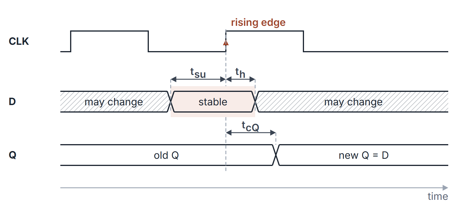
- Setup time : data must be stable at least before the active clock edge.
- Hold time : data must remain stable at least after the edge.
- Clock-to-Q : delay from the edge to the new output.
- Violation risks metastability. Minimum clock period also needs combinational delay between FFs: (plus skew terms in fuller models).
How it works
Master-slave intuition
Master latch samples while clock is high (or low); slave updates on the opposite phase, yielding overall edge behaviour. Modern FFs use more robust edge circuits; exam diagrams still show master-slave.
Race-around in a level-triggered JK
Build a JK from a gated SR latch by feeding back the outputs: and , enabled while the clock is high. With the latch toggles, the new output feeds back, and it toggles again, as long as the clock stays high. The output oscillates whenever the clock pulse width exceeds the loop's propagation delay; the final value when the clock falls is unpredictable. This is the race-around condition. The cures are a master-slave JK (the master is closed while the slave changes) or an edge-triggered JK. A very narrow clock pulse also avoids it but is fragile.
Conversions
Procedure: write the characteristic table of the target flip-flop (inputs and to ); for each row, read from the available flip-flop's excitation table the inputs that produce that ; minimise those inputs as functions of the target inputs and .
| Target from available | Wiring |
|---|---|
| D from JK | , |
| T from JK | |
| JK from D | |
| T from D | |
| D from T | |
| JK from T | |
| JK from SR | , |
| SR from JK | , (valid while ) |
Check of T from JK: . Check of D from JK: .
Timing
For a path from flip-flop 1 through logic to flip-flop 2, both on the same clock:
The setup check uses the slowest path and depends on . The hold check uses the fastest path and does not involve the clock period at all, so slowing the clock never fixes a hold violation. With clock skew (positive when the receiving FF sees the clock later):
Positive skew helps setup and hurts hold. Many timing problems ignore skew; include it only when the stem names it.
Algorithms and pseudocode
Next-state functions for a bank of FFs use the characteristic equations. EXCITE inverts any characteristic function by trying every input combination.
D-NEXT(D)
1  return D

T-NEXT(Q, T)
1  return Q XOR T

JK-NEXT(Q, J, K)
1  return (J AND NOT Q) OR ((NOT K) AND Q)

EXCITE(NEXT, Q, Qplus, inputs)   // which inputs drive Q to Qplus
1  ok <- empty list
2  for each assignment x of inputs
3      if NEXT(Q, x) = Qplus then append x to ok
4  return ok    // an input is X if it varies across ok while the others are fixed
For a flip-flop with inputs, EXCITE does evaluations per row, 4 rows in all.
Cost of a conversion. Best, average and worst case are the same, because no step depends on the data. A target flip-flop with inputs has a characteristic table of rows (its inputs and ). Each row needs one excitation lookup for the available flip-flop, or EXCITE evaluations if it has inputs. JK from T has 8 rows and 16 evaluations; D from JK has 4 rows and 16 evaluations. Minimisation is then a K-map on variables.
Mathematical explanation
A flip-flop is a finite automaton with two states and inputs that determine the transition function . Excitation tables invert (with don't-cares where two inputs work).
Why the JK equation has that form. when and (set or toggle), or when and (hold or set). That is . In the same way, for SR: set, or stay at 1 unless reset.
Worked examples
Example 1: JK with
(set).
Example 2: toggle
T FF with each cycle: state sequence (divide-by-2). A D flip-flop with behaves the same way, as does a JK with .
Example 3: excitation for with JK
Need , don't-care: resets and toggles, and both give 0.
Example 4: period constraint
If , , , then (ignore skew) and .
Example 5: setup, hold and skew together
Take , , , , (all ns).
- No skew: , so . Hold: , met with 1 ns of margin.
- Skew : (); hold needs , met with no margin.
- Skew : , but hold needs , which fails at every clock frequency.
Example 6: a JK sequence
Start at and apply on successive edges. The states after each edge are (set), (toggle), (hold), (toggle), (reset).
Example 7: convert a T flip-flop into JK
Target JK, available T, so row by row. With , , so . With , , so . Together . Check the toggle row : .
Example 8: SR latch sequence
A NOR latch starts with . Inputs in turn give . Applying would give , and a following would leave the result to the race.
Important properties and observations
- Latch vs FF: level vs edge; never clock a latch with the same policy as an edge FF without analysing transparency races.
- Asynchronous preset/clear override the clocked path when asserted.
- Metastability: resolving time is unbounded in theory; practical synchronizers cascade FFs.
- D is the simplest to design with (excitation equals the next state); JK gives the most don't-cares in excitation maps and often the simplest input logic.
Common misconceptions.
- "SR=11 stores 1." Forbidden; undefined/race.
- "Hold time is always zero." Not true for all libraries; still examined conceptually.
- "A T flip-flop needs on every edge." toggles; to hold, set .
- "A hold violation can be fixed by slowing the clock." The hold check does not contain ; only more delay on the short path (or less skew) helps.
- "Master-slave JK has race-around." The master-slave structure is what removes it.
GATE examination perspective
- CHARACTERISTIC VS EXCITATION. Do not swap the tables.
- FORBIDDEN SR. Spot (NOR) or (NAND).
- CONVERSION. Target characteristic, then available excitation, then minimise.
- RACE-AROUND. Level-triggered JK with and a wide clock pulse.
- TIMING. Setup uses maximum propagation delays; hold uses minimum contamination delays and is independent of . Apply skew with the stated sign convention.
- SEQUENCES. Apply the characteristic equation edge by edge.
All numerical timing examples that give only one use an idealised fixed-delay model: . In a real timing analysis, use maximum propagation delay for setup and minimum clock-to-Q contamination delay for hold. If capture clock arrival minus launch clock arrival is , setup requires , while hold requires .
Summary
Sources
- M. Morris Mano, M. D. Ciletti, Digital Design, 5th ed., Pearson, 2013: Chapter 5, Sections 5.3 and 5.4 (latches; flip-flops).