
Introduction
Pipelining overlaps the execution of several instructions, the way an assembly line overlaps the building of several cars. The work of one instruction is cut into stages (for example fetch, decode, execute, memory access, write back). Each stage finishes its part in one clock cycle and hands the partial result to the next stage through a pipeline register (latch). Once the pipeline is full, one instruction finishes every cycle, although each individual instruction still needs cycles.
Pipelining improves throughput (instructions completed per unit time). It does not shorten, and usually lengthens, the latency of a single instruction. The key distinction is between those two ideas, and the clock period must be computed correctly when stages are unequal or latches add delay. Stalls caused by dependences and branches are the subject of Pipeline Hazards; this note covers the ideal pipeline and the performance arithmetic that hazards plug into.
Prerequisites
- CPU Datapath and Instruction Cycle: the fetch, decode, execute steps that become pipeline stages, and the register file, ALU and memory interfaces each stage uses.
Core concepts
| Term | Meaning |
|---|---|
| Stage | One step of instruction processing done by its own hardware in one cycle |
| Depth | Number of stages |
| Pipeline register (latch, buffer) | Register between two stages that holds the outputs of the earlier stage for the later one |
| Latch overhead | Delay added by a pipeline register (setup time plus clock-to-output delay) |
| Clock period | Time of one pipeline cycle: , where is the logic delay of stage |
| Fill (warm-up) | The first cycles, before the first instruction completes |
| Steady state | One instruction enters and one leaves every cycle |
| Drain | The last cycles, when no new instruction enters |
| Latency | Time from the start to the end of one instruction: |
| Throughput | Instructions completed per unit time: in steady state |
| CPI | Average clock cycles per instruction; 1 for an ideal pipeline in steady state |
Clock convention used in all Gate CS Mastery notes. "Stage delay" means the logic delay of the stage alone. The pipeline clock period is the largest stage delay plus the latch delay. A non-pipelined (single-cycle) processor has no inter-stage latches, so its instruction time is the sum of the stage delays. If a question says the non-pipelined processor also pays one register delay per instruction, add it once; follow the question.
Ideal-pipeline assumptions. Every stage takes one cycle, stages are independent hardware, every instruction passes through every stage, and there are no stalls. Each assumption fails somewhere in practice: stages are unequal, memory is shared (structural hazard), instructions depend on one another (data hazard), and branches change the flow (control hazard).
The classic five-stage RISC pipeline
| Stage | Work |
|---|---|
| IF | Fetch the instruction at PC from the instruction memory (or I-cache); PC <- PC + 4 |
| ID | Decode; read source registers from the register file; sign-extend the immediate |
| EX | ALU operation, or effective-address calculation for loads and stores, or branch comparison |
| MEM | Data memory read (load) or write (store); nothing for ALU instructions |
| WB | Write the result into the destination register |
Each stage needs its own resources in the same cycle, which is why such designs have separate instruction and data caches and a register file that can be read and written in one cycle (write in the first half, read in the second half).
How it works
Draw a space-time diagram: rows are instructions, columns are clock cycles, and each cell names the stage an instruction occupies. Instruction (counting from 1) enters IF in cycle and leaves WB at the end of cycle .
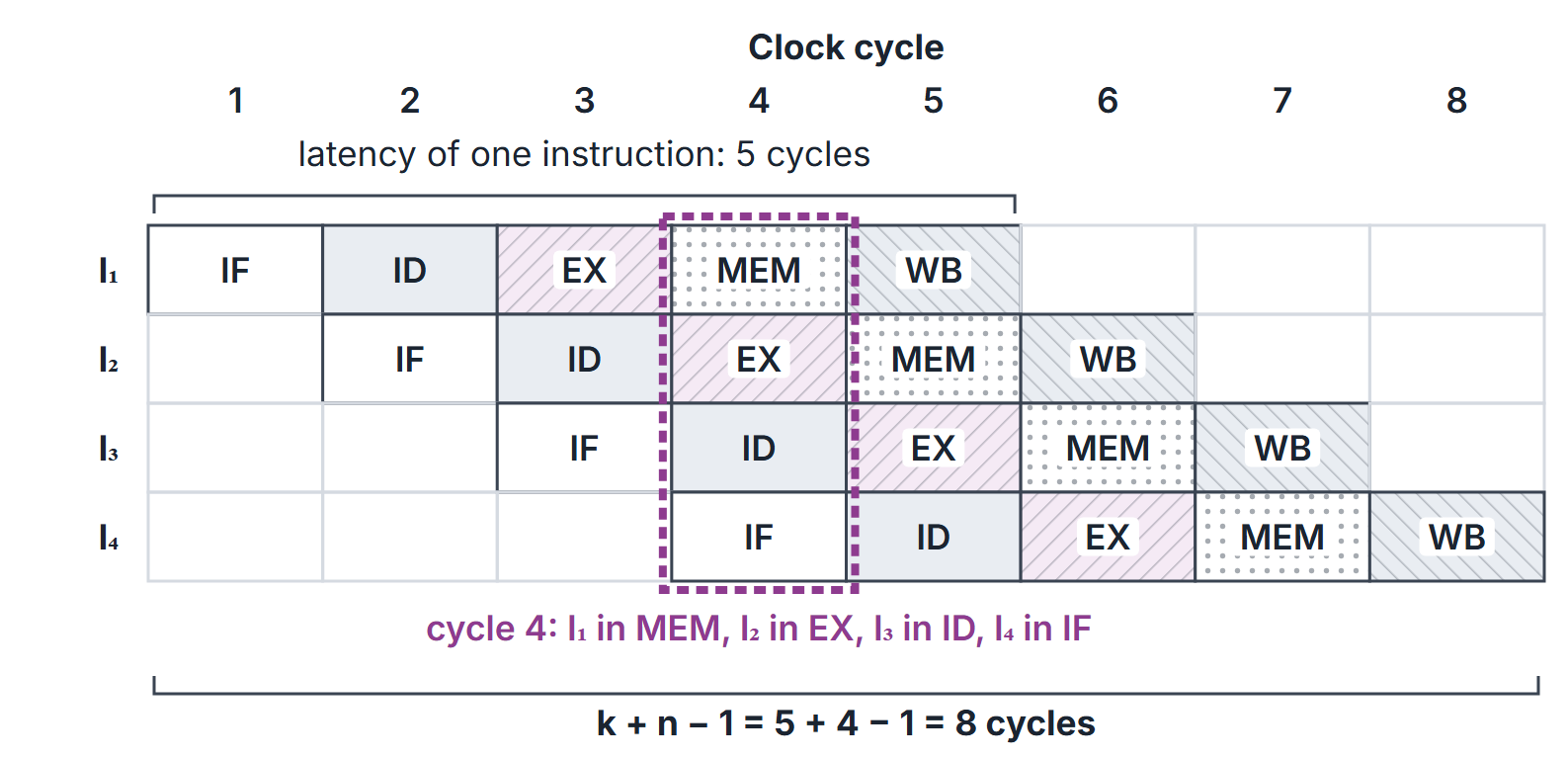
Reading Figure 1 column by column: in cycle 4, is in MEM, in EX, in ID and in IF. In cycle 5 all five stages would be busy if a fifth instruction existed. The first result appears at the end of cycle 5 ( cycles); after that one result appears per cycle.
Algorithms and pseudocode
The counting procedure below gives the cycle count of an ideal pipeline and shows where each term comes from. Instructions are numbered from 1.
PIPELINE-CYCLES(n, k)
  // n instructions, k stages, no stalls
  first <- k              // I1 completes at the end of cycle k
  rest  <- n - 1          // each later instruction completes one cycle after its predecessor
  return first + rest     // k + n - 1

PIPELINE-TIME(n, tau[1..k], d)
  tp <- max(tau[1..k]) + d
  return PIPELINE-CYCLES(n, k) * tp
For , scanning all stage delays costs in every case and auxiliary workspace excluding the supplied stage-delay vector. No average distribution is needed because every entry is scanned. The formula assumes no stalls; add any stall cycles separately.
Mathematical explanation
Let be the number of stages, the stage logic delays, the latch delay and the number of instructions.
Clock period.
Pipelined time for instructions (no stalls).
Non-pipelined time. A single-cycle processor spends per instruction, so .
Speedup.
When all stages take the same time and , , so
So is an upper bound on the speedup of a -stage pipeline, for , reached only in the limit and only with perfectly balanced stages and no latch overhead. With unequal stages or latch delay, the limit is when stages are unequal or latch delay is positive. For , speedup is exactly 1.
Efficiency and throughput. Efficiency (fraction of stage-cycles doing useful work) is , which equals in the balanced case. Throughput is , which tends to .
With stalls. If the pipeline loses stall cycles per instruction on average, the steady-state CPI is . Measuring against the same instruction count,
For balanced stages with , . The fill time is usually ignored for large ; keep it when the question gives a small .
Comparing with a multicycle processor. A multicycle (non-pipelined) design uses a short clock and different numbers of cycles per instruction class. Its time per instruction is , where for class frequencies and cycle counts . Then .
Performance equation. For any processor, CPU time instruction count CPI clock period. Pipelining lowers the CPI towards 1 with a clock close to the multicycle clock; a single-cycle design has CPI 1 with a long clock.
Worked examples
Example 1: unequal stages and latch delay
A four-stage pipeline has stage delays 60, 50, 90 and 80 ps and a latch delay of 10 ps. The non-pipelined processor takes ps per instruction.
- Clock period: ps.
- 1000 instructions, pipelined: ps ns.
- Non-pipelined: ps.
- Speedup: . For very large it approaches , well below the stage count 4.
- Throughput in steady state: one instruction per 100 ps, that is instructions per second.
- Latency of one instruction: ps, longer than the 280 ps of the non-pipelined design.
Example 2: splitting the bottleneck stage
Split the 90 ps stage of Example 1 into two stages of 45 ps each. The stage delays become 60, 50, 45, 45, 80 ps, so ps and .
- 1000 instructions: ps.
- Improvement over the four-stage pipeline: .
- The new bottleneck is the 80 ps stage. Splitting the 90 ps stage cannot bring the clock below ps, and every extra stage adds one more latch delay to the latency (now ps).
Example 3: how many instructions for a target speedup
A five-stage pipeline has equal stages and no latch overhead, so . For we need , that is . Check: exactly, and . Even with , : the bound 5 is never reached.
Example 4: CPI with load and branch stalls
In a five-stage pipeline with forwarding, 30% of instructions are loads, and 40% of the loads are immediately followed by an instruction that uses the loaded value (1 stall cycle each). 15% of instructions are branches; 60% of the branches are taken, the pipeline predicts not taken, and a taken branch costs 2 stall cycles.
- Load stalls per instruction: .
- Branch stalls per instruction: .
- CPI .
Now suppose the pipelined clock period is 2 ns and a single-cycle processor needs 8 ns per instruction. For 100 instructions in this 5-stage pipeline, the 30 stall cycles give cycles, so the pipelined time is ns; the single-cycle baseline is ns. Speedup is . The value is the steady-state approximation, which neglects the 4 fill cycles.
Example 5: pipelined versus multicycle
A multicycle processor with a 100 ps clock takes 5 cycles for loads, 4 for stores, 4 for ALU instructions and 3 for branches. The mix is 25% loads, 10% stores, 50% ALU and 15% branches.
- .
- A pipelined version needs a 110 ps clock (latch overhead) and achieves CPI 1.2.
- Speedup: .
Important properties and observations
- Throughput versus latency. Pipelining raises throughput; the latency of one instruction stays the same or grows ().
- Speedup is bounded by depth. generally; for finite when . For , exactly, and even as .
- The slowest stage sets the clock. Speeding up any other stage does not change . Balancing stages matters more than adding stages.
- Deeper is not always faster. Each extra stage adds a latch delay and makes hazards cost more cycles (a branch resolved later wastes more fetches). The useful depth is limited.
- Fill and drain matter only for small . For much larger than , .
- Same instruction set, same results. Pipelining is an implementation technique; it does not change the program's meaning, which is why hazards must be handled in hardware or by the compiler.
- Common misconceptions.
- "A 5-stage pipeline is 5 times faster." Only with balanced stages, no latch delay, no stalls and infinitely many instructions.
- "Pipelining reduces the time of each instruction." It reduces the average time between completions.
- "CPI of a pipeline is ." Steady-state CPI is 1 plus stalls; each instruction's latency is cycles.
Related material. A superscalar processor issues more than one instruction per cycle into multiple pipelines, so its ideal CPI is below 1 (ideal IPC equals the issue width). Out-of-order execution and dynamic scheduling are beyond the GATE syllabus wording; they appear in Hamacher, Section 8.6.
GATE examination perspective
- CLOCK PERIOD. Take the maximum stage delay and add the latch delay once; never average the stage delays.
- NON-PIPELINED TIME. Usually the sum of stage delays without latches; read whether the question adds a register delay.
- FILL CYCLES. For instructions use cycles, not and not . With a small the difference matters.
- SPEEDUP VERSUS THROUGHPUT. Speedup is a ratio of times; throughput is a rate (instructions per second). A question may ask for one and give options for the other.
- STAGE SPLITTING. Recompute from the new maximum after splitting, and count the extra stage in .
- STALLS IN CPI. Weight each stall by the fraction of instructions it affects: CPI .
- BASELINE. Check whether the speedup is relative to a single-cycle, a multicycle, or an ideal pipelined processor; each gives a different number.
Summary
Sources
- C. Hamacher, Z. Vranesic, S. Zaky, Computer Organization, 5th ed., McGraw-Hill, 2002: Chapter 8 (Pipelining), Sections 8.1 (Basic Concepts, including 8.1.2 Pipeline Performance), 8.6 (Superscalar Operation) and 8.8 (Performance Considerations).
- D. A. Patterson, J. L. Hennessy, Computer Organization and Design: The Hardware/Software Interface, 5th ed. (MIPS edition), Morgan Kaufmann, 2013: Sections 4.5 (An Overview of Pipelining) and 4.6 (Pipelined Datapath and Control).
- W. Stallings, Computer Organization and Architecture, 10th ed., Pearson, 2016: Section 14.4 (Instruction Pipelining).