
Introduction
A machine instruction is a bit pattern that the processor decodes and executes: it names an operation (the opcode) and the operands the operation uses. The instruction set architecture (ISA) is the full list of instructions, their formats, the registers and the memory model a programmer can rely on. The instruction format fixes how the bits of an instruction are divided into fields.
GATE asks you to size the fields of a format (how many bits the opcode, register and immediate fields need, and what range the immediate can hold), to count how many instructions of each kind an expanding opcode scheme allows, to compute where an instruction sits in memory, and to compare the code produced by 3-, 2-, 1- and 0-address machines for the same expression. How each operand field is turned into an address is the subject of Addressing Modes.
Prerequisites
- Number Systems and Base Conversion: a field of bits can hold distinct codes, and choosing one of items needs bits.
Core concepts
What an instruction contains
- Opcode: which operation to perform.
- Source operand specifiers: register numbers, memory addresses, or an immediate constant held in the instruction itself.
- Destination specifier: where the result goes.
- Next instruction: implicit (the program counter (PC) simply advances) except for branches, jumps, calls and returns.
Kinds of instructions
| Kind | Examples | Effect |
|---|---|---|
| Data transfer | LOAD, STORE, MOVE, PUSH, POP | Copy between registers and memory |
| Arithmetic and logic | ADD, SUB, AND, OR, shift, rotate, compare | Compute and set condition codes (flags) |
| Control transfer | Branch (conditional), jump, CALL, RETURN | Change the PC |
| Input/output | IN, OUT (isolated I/O) or ordinary loads and stores (memory-mapped I/O) | Move data to and from devices |
| System | Trap or software interrupt, halt | Enter the operating system, stop |
Subroutine call and return. CALL saves the return address (the address of the next instruction) and loads the PC with the subroutine address; RETURN restores the saved address. In stack-based CALL/RETURN, CALL pushes and RETURN pops the return address. Link-register ISAs instead save it in a register; software preserves it, often on a stack, when further calls require it.
Number of addresses per instruction
| Style | Typical arithmetic instruction | Where operands live |
|---|---|---|
| 3-address | ADD X, Y, Z (X Y + Z) | All three named |
| 2-address | ADD X, Y (X X + Y) | One source is also the destination |
| 1-address (accumulator) | ADD Y (AC AC + Y) | The accumulator AC is implied |
| 0-address (stack) | ADD (pop two, push the sum) | The top of the stack is implied |
Fewer addresses mean shorter instructions but more of them. A load-store (register-register) machine allows memory operands only in LOAD and STORE; arithmetic works on registers. A register-memory machine allows one memory operand in an arithmetic instruction.
RISC and CISC
| Feature | RISC | CISC |
|---|---|---|
| Instruction length | Fixed (for example 32 bits) | Variable |
| Memory operands | LOAD and STORE only | Many instructions |
| Addressing modes | Few, simple | Many, some complex |
| Registers | Many general-purpose registers | Fewer |
| Control unit | Usually hardwired | Often microprogrammed |
| Typical CPI | Close to 1 with pipelining | Several cycles per instruction |
Fixed and variable length
Fixed-length formats make fetching and decoding simple and suit pipelining, at the cost of wasted bits in short instructions. Variable-length formats pack code densely but complicate decoding. Expanding opcodes are a middle path: the instruction length is fixed, but instructions with fewer operands use the freed operand bits as extra opcode bits.
How it works
Sizing the fields
For a fixed-length instruction of bits:
- opcode bits ;
- each register field ;
- each memory-address field ;
- the immediate field gets whatever is left: minus all other fields.
An immediate field of bits holds to unsigned, or to in two's complement.
Expanding opcodes
Start from the format with the most operands. Of its opcode patterns, use some and reserve the rest as escape prefixes. Each reserved prefix, followed by one operand field of bits now used as opcode, yields patterns for the next format, and so on.
Algorithms and pseudocode
EXPANDING-OPCODE-CAPACITY(L, a, wanted[])   // L-bit instruction, a-bit operand fields
                                             // wanted[k] = instructions with k operands,
                                             // k from the largest count down to 0
// word-RAM: best Theta(1), worst Theta(kmax+1), O(1) auxiliary space
  free <- 2 ^ (L - a * kmax)                 // patterns for the kmax-operand format
  for k <- kmax down to 0
      if wanted[k] > free  return "impossible"
      free <- free - wanted[k]               // patterns left unused at this level
      if k > 0  free <- free * 2 ^ a         // each one becomes a prefix for the next level
  return free                                // zero-operand patterns still unused
The maximum number of instructions of the last kind is the value of free just before it is consumed.
Cost model. For word-sized arithmetic, immediate rejection is best case; scanning all operand counts is worst case, with auxiliary workspace excluding wanted. An average case needs an input distribution. Large- integer shifts and arithmetic have additional bit costs.
Mathematical explanation
Expanding-opcode count. With an -bit instruction, -bit operand fields and instructions that have operands, the number of patterns available for -operand instructions is
A design is possible exactly when at every level. An equivalent check counts the fraction of the code space used: each -operand instruction uses of the patterns, and the fractions must add up to at most 1:
Instruction addresses. In a byte-addressable memory, if every instruction is bytes long and the program starts at address , instruction number (counting from 1) starts at .
Worked examples
Example 1: sizing a format
A processor has 32-bit instructions, 64 registers and 45 distinct instructions. One format holds an opcode, two register fields and an immediate.
- Opcode: bits. Registers: bits each, 12 in total.
- Immediate: bits.
- Range: to unsigned; to signed.
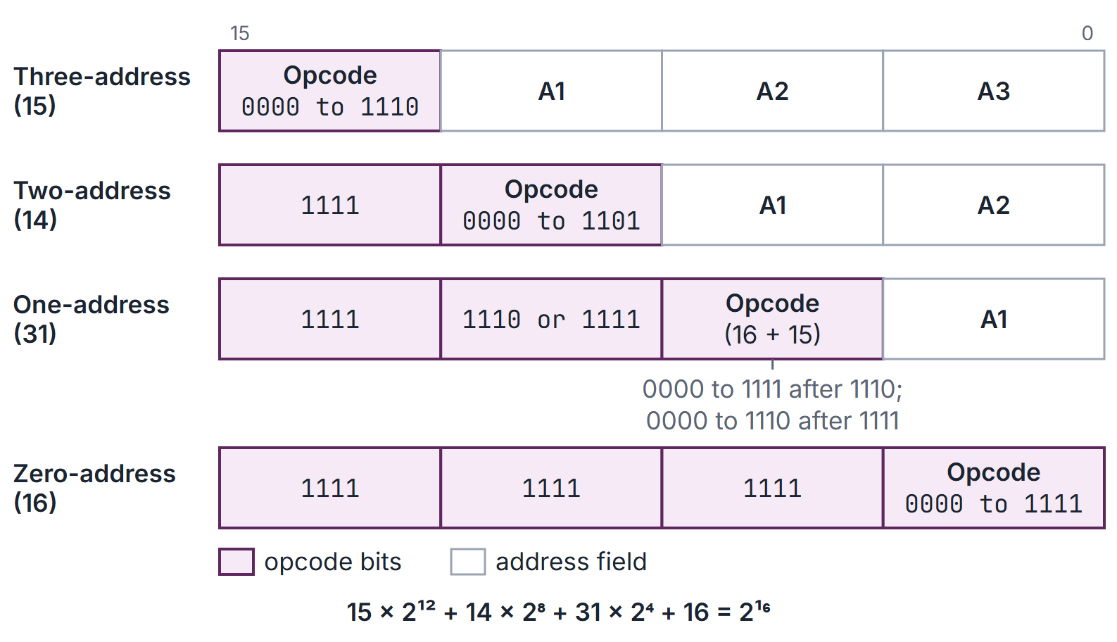
Example 2: expanding opcode (Figure 1)
A 16-bit instruction has 4-bit operand fields. The designer wants 15 three-address instructions, 14 two-address instructions and 31 one-address instructions. How many zero-address instructions are possible?
- Three-address: patterns; 15 are used, so 1 is left (1111).
- Two-address: patterns; 14 used (1111 0000 to 1111 1101), 2 left.
- One-address: patterns; 31 used, 1 left (1111 1111 1111).
- Zero-address: .
Check with the code-space sum: . The space is used exactly, so 16 is the maximum.
A variant: if only 13 two-address instructions were wanted, 3 prefixes would remain, giving 48 one-address patterns.
Example 3: the same expression on different machines
Evaluate , all variables in memory. Count instructions and data-memory references (all operand-stack entries used by the zero-address program, maximum depth 3, are held internally, so stack pushes/pops do not count as data-memory accesses).
| Style | Program | Instructions | Data references |
|---|---|---|---|
| 3-address | ADD T, A, B; ADD X, C, D; MUL X, X, T | 3 | 9 |
| 2-address | MOV T, A; ADD T, B; MOV X, C; ADD X, D; MUL X, T | 5 | 13 |
| 1-address | LOAD A; ADD B; STORE T; LOAD C; ADD D; MUL T; STORE X | 7 | 7 |
| 0-address | PUSH A; PUSH B; ADD; PUSH C; PUSH D; ADD; MUL; POP X | 8 | 5 |
| Load-store | LOAD R1, A; LOAD R2, B; ADD R1, R1, R2; LOAD R2, C; LOAD R3, D; ADD R2, R2, R3; MUL R1, R1, R2; STORE X, R1 | 8 | 5 |
The 2-address count is highest because each two-operand ADD or MUL reads both operands and writes the result back to memory. The stack program is the postfix form .
Example 4: where an instruction sits
A program of 24-bit (3-byte) instructions starts at byte address 300. Instruction 10 starts at . If the machine instead pads every instruction to a 4-byte aligned word, instruction 10 starts at , and the program of 10 instructions ends at 339 instead of 329.
Example 5: is a design possible?
A 12-bit instruction with 4-bit address fields should support 15 two-address and 100 one-address instructions. Two-address: patterns, 15 used, 1 left. One-address: . Impossible. The code-space sum agrees: .
Important properties and observations
- Field sizes are ceilings of logarithms. 45 operations need 6 bits, not 5.5.
- The immediate takes the leftover bits, and its signed range is half below zero.
- Expanding opcodes trade operands for opcode space; every reserved prefix multiplies by at the next level.
- Fewer addresses, shorter instructions, longer programs: the stack machine needs the most instructions for the same expression, the 3-address machine the fewest.
- Load-store machines have more instructions than memory-operand machines but fewer memory references and simpler pipelines.
- CALL must save the return address; a stack lets calls nest and supports recursion.
- Common misconceptions.
- "Zero-address instructions have no operands." The operands are implicit (the stack top).
- "The maximum count of the last format is minus the others." Count level by level: unused patterns multiply by .
- "A 14-bit immediate reaches 16383 when signed." Signed it reaches only 8191.
GATE examination perspective
- FIELD SIZING. Ceiling of for opcode and registers, leftover for the immediate; state signed or unsigned range.
- EXPANDING OPCODE. Walk from the most operands down: unused patterns times ; confirm with .
- ADDRESS STYLE. Write the program for each style; count instructions, then memory references per instruction.
- INSTRUCTION ADDRESS. Start size; watch whether instructions are padded to word boundaries.
- RISC OR CISC. Fixed length, load-store and many registers mark RISC.
- PROGRAM SIZE. Instructions times instruction length, rounded to whole bytes or words.
Summary
Sources
- C. Hamacher, Z. Vranesic, S. Zaky, Computer Organization, 5th ed., McGraw-Hill, 2002: Chapter 2, Sections 2.4 (Instructions and Instruction Sequencing, including 2.4.3 Basic Instruction Types), 2.8 (Stacks and Queues), 2.9 (Subroutines) and 2.12 (Encoding of Machine Instructions).
- D. A. Patterson, J. L. Hennessy, Computer Organization and Design: The Hardware/Software Interface, 5th ed. (MIPS edition), Morgan Kaufmann, 2013: Section 2.5 (Representing Instructions in the Computer).
- W. Stallings, Computer Organization and Architecture, 10th ed., Pearson: Sections 12.1 (Machine Instruction Characteristics), 12.4 (Types of Operations), 13.3 (Instruction Formats), 15.4 (Reduced Instruction Set Architecture) and 15.8 (RISC versus CISC Controversy).