
Introduction
IP delivers datagrams between hosts, unreliably. The transport layer turns this into communication between processes, identified by 16-bit port numbers, and optionally adds reliability. The Internet has two main transport protocols:
- UDP adds only ports and a checksum to IP: no connection, no acknowledgement, no ordering, no flow or congestion control. Each
sendis one datagram. It suits short request-response exchanges (DNS), real-time media and protocols that manage their own reliability. - TCP gives a reliable, ordered, full-duplex byte stream over a connection: it numbers bytes, acknowledges them, retransmits lost data, and paces the sender to the receiver (flow control) and to the network (congestion control).
Both protocols are described by what they carry and by how a TCP connection is opened, used and closed: headers, sequence and acknowledgement numbers, the three-way handshake, connection release, the state machine and the retransmission timer. Flow control and congestion control have their own notes.
Prerequisites
- Layering, OSI and TCP/IP Reference Models: the transport layer, encapsulation and end-to-end delivery.
Core concepts
Ports and demultiplexing
| Protocol | A socket is identified by |
|---|---|
| Unconnected UDP (usual default) | (destination IP, destination port): datagrams from any source to that endpoint reach the same socket; connected UDP records a peer and filters other source endpoints |
| TCP | (source IP, source port, destination IP, destination port): each connection has its own socket, so one server port serves many clients |
Well-known server ports: 20 and 21 FTP, 22 SSH, 23 Telnet, 25 SMTP, 53 DNS, 80 HTTP, 443 HTTPS.
UDP header and checksum
| Field | Bits |
|---|---|
| Source port | 16 |
| Destination port | 16 |
| Length (header + data, bytes; at least 8) | 16 |
| Checksum | 16 |
The checksum is the Internet checksum over a pseudo-header (source IP, destination IP, a zero byte, protocol 17, UDP length), the UDP header (with checksum 0) and the data, padded with a zero byte if odd. Including the IP addresses guards against delivery to the wrong host. Over IPv4 the checksum is optional: a transmitted value of 0 means "not computed", so a computed result of 0 is sent as 0xFFFF.
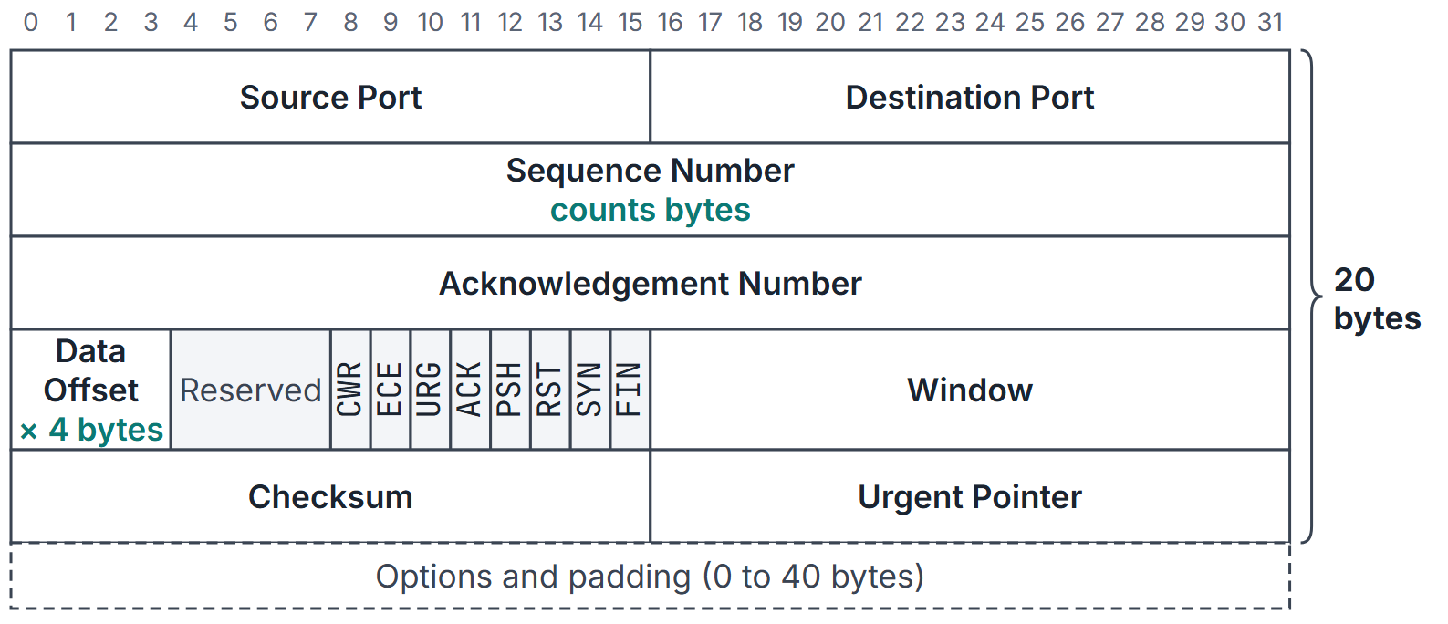
TCP header
| Field | Bits | Meaning |
|---|---|---|
| Source port, destination port | 16 each | Process endpoints |
| Sequence number | 32 | Number of the first data byte in this segment (or the ISN on a SYN) |
| Acknowledgement number | 32 | Next byte expected from the other side; valid when ACK = 1 |
| Data offset | 4 | Header length in 4-byte words: 5 to 15, so 20 to 60 bytes |
| Reserved | 4 | Zero |
| Flags | 8 | CWR, ECE, URG, ACK, PSH, RST, SYN, FIN |
| Window | 16 | Bytes the sender of this segment is willing to receive (flow control) |
| Checksum | 16 | Internet checksum over pseudo-header (protocol 6), header and data; mandatory |
| Urgent pointer | 16 | Valid when URG = 1 |
| Options | 0 to 320 | MSS (on SYN), window scale, SACK permitted, timestamps |
Sequence and acknowledgement numbers
- TCP numbers bytes, not segments. A segment with sequence number and data bytes carries bytes to ; the next segment starts at .
- The initial sequence number (ISN) is chosen at connection set-up, not fixed at 0, to keep segments from an old connection with the same ports from being taken as new.
- SYN and FIN each consume one sequence number, even when they carry no data; any payload bytes consume their own sequence numbers as usual. Pure ACKs consume none.
- Acknowledgements are cumulative: ACK number means every byte up to has arrived in order.
Connection establishment: the three-way handshake
- Client to server: SYN, seq = .
- Server to client: SYN + ACK, seq = , ack = .
- Client to server: ACK, seq = , ack = (it may already carry data).
Three messages are the minimum that let both sides learn that the other has received their ISN. A two-way exchange would leave the server unable to tell a fresh SYN from a delayed duplicate of an old one.
Connection release
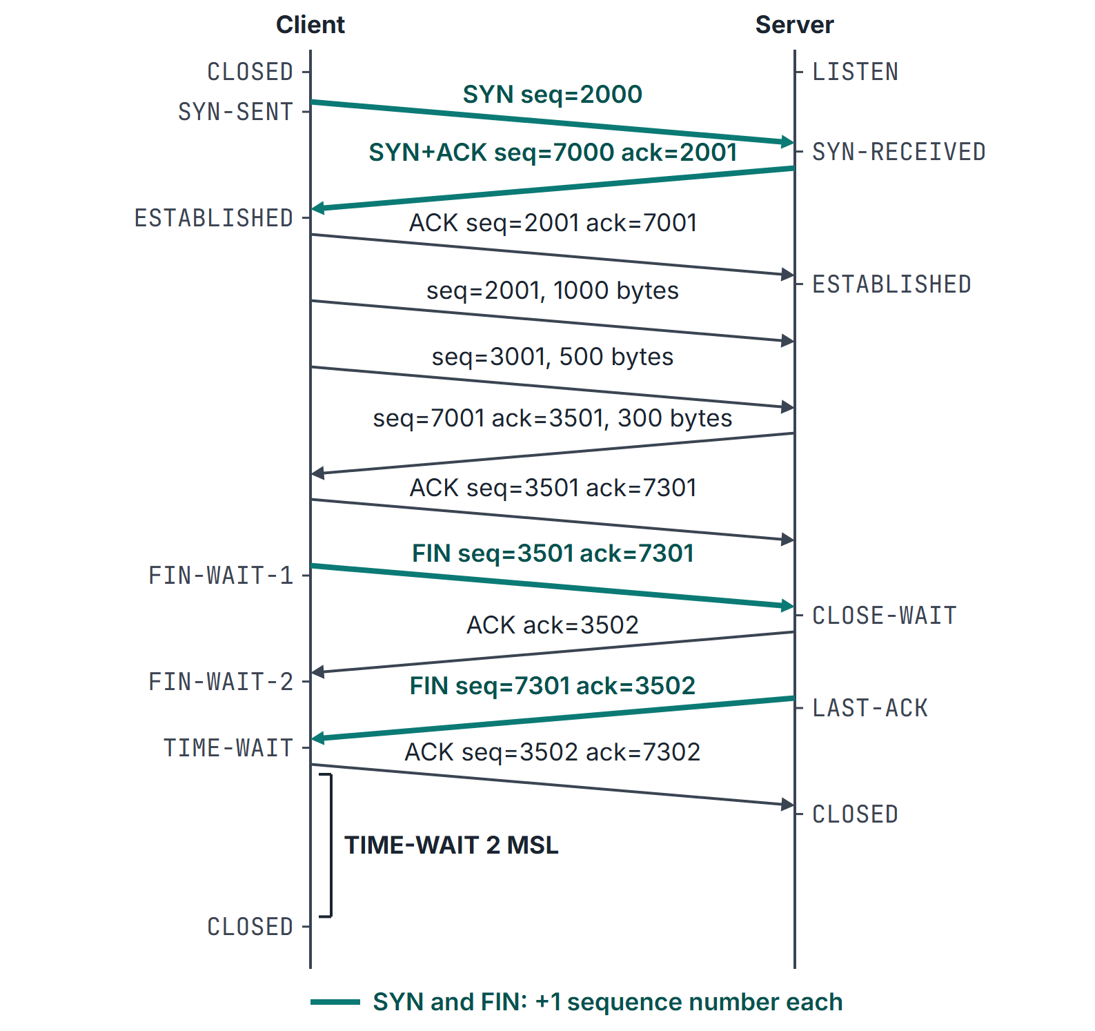
Each direction is closed separately (a half-close): the side that has finished sends FIN, the other acknowledges it, and may keep sending until it sends its own FIN. The usual exchange is four segments, FIN, ACK, FIN, ACK, or three when the second FIN rides on the first ACK. The side that closes first waits in TIME-WAIT for (maximum segment lifetime; RFC 9293 takes MSL as 2 minutes) before forgetting the connection, so that its last ACK can be resent if lost and old duplicates die out.
The state machine
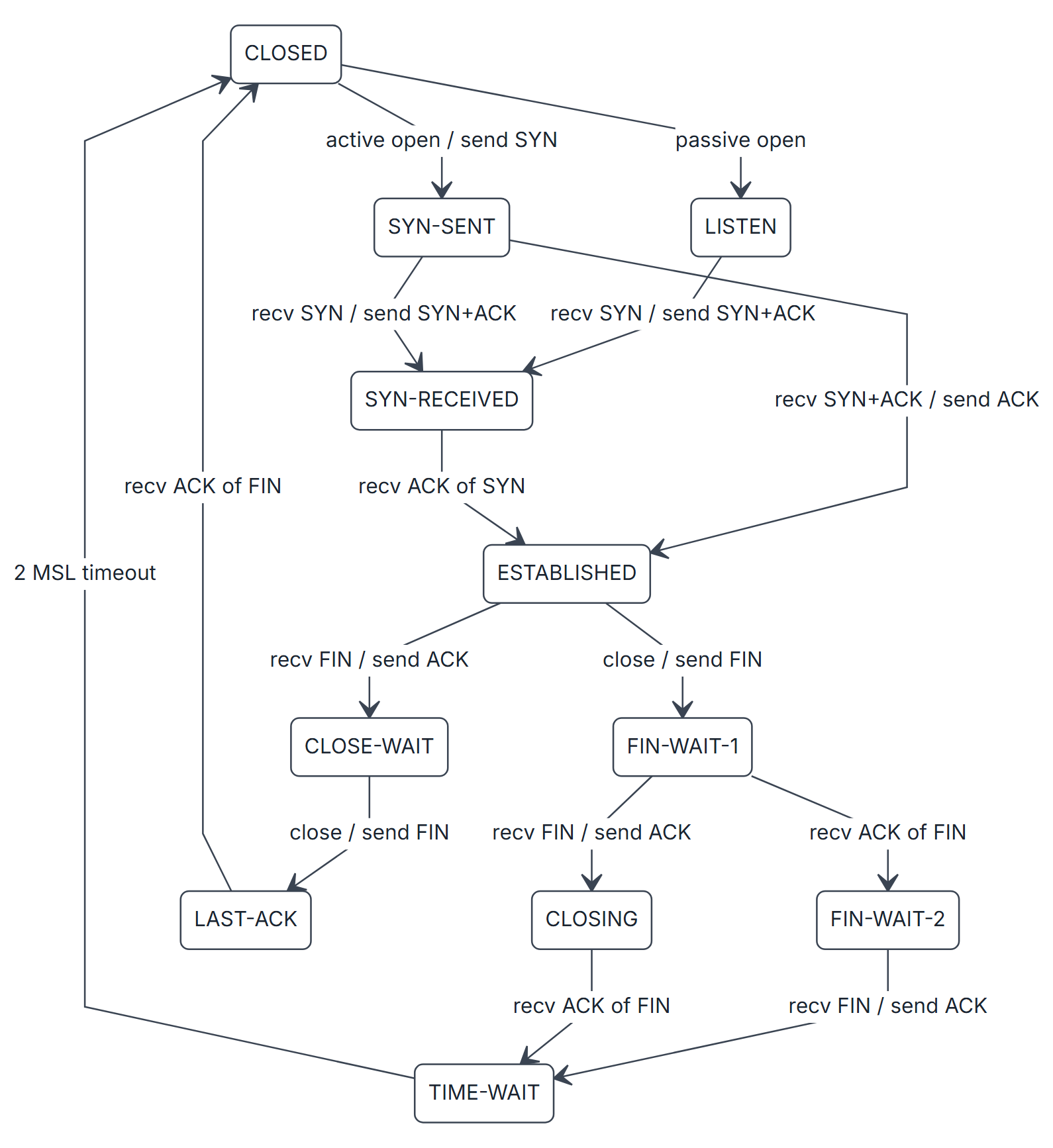
Eleven states. The active closer passes through FIN-WAIT-1, FIN-WAIT-2 (or CLOSING on a simultaneous close) and TIME-WAIT; the passive closer through CLOSE-WAIT and LAST-ACK. SYN-SENT to SYN-RECEIVED is the simultaneous open, where both sides send SYNs at once.
The retransmission timer
TCP retransmits a segment if its acknowledgement does not arrive within the retransmission timeout (RTO), estimated from measured round-trip times (RFC 6298):
- first measurement: , ;
- later measurements, RTTVAR first, using the old SRTT: , then ;
- , with clock granularity , rounded up to at least 1 second.
Karn's algorithm: do not take RTT samples from retransmitted segments (the ACK could belong to either copy), and double the RTO after each timeout until a new sample is taken. The original TCP specification (RFC 793) used only a weighted average, with about 0.8 to 0.9, and with about 1.3 to 2.0 (within fixed bounds); a problem must state which rule and which constants it uses.
Mathematical explanation: counting bytes
For a connection with client ISN and server ISN , after the client has sent data bytes and the server :
and the client's FIN carries seq and is acknowledged with . The terms are the SYN and the FIN.
Header overheads. With no options, a TCP segment over IPv4 carries 40 bytes of headers (20 IP + 20 TCP), a UDP datagram 28 (20 + 8). The maximum segment size advertised over Ethernet is usually bytes.
Worked examples
Example 1: a whole connection
Client ISN 2000, server ISN 7000 (Figure 2).
| # | Direction | Flags | Seq | Ack | Data bytes |
|---|---|---|---|---|---|
| 1 | C to S | SYN | 2000 | n/a | 0 |
| 2 | S to C | SYN, ACK | 7000 | 2001 | 0 |
| 3 | C to S | ACK | 2001 | 7001 | 0 |
| 4 | C to S | ACK | 2001 | 7001 | 1000 (2001 to 3000) |
| 5 | C to S | ACK | 3001 | 7001 | 500 (3001 to 3500) |
| 6 | S to C | ACK | 7001 | 3501 | 300 (7001 to 7300) |
| 7 | C to S | ACK | 3501 | 7301 | 0 |
| 8 | C to S | FIN, ACK | 3501 | 7301 | 0 |
| 9 | S to C | ACK | 7301 | 3502 | 0 |
| 10 | S to C | FIN, ACK | 7301 | 3502 | 0 |
| 11 | C to S | ACK | 3502 | 7302 | 0 |
Segments 3, 7 and 11 are pure ACKs and do not advance the sequence number; the FINs at 3501 and 7301 do.
Example 2: UDP checksum
A UDP datagram from 192.168.10.5:5353 to 172.16.30.40:53 carries the 4 bytes "GATE". Length = 12. The 16-bit words summed are:
| Part | Words |
|---|---|
| Pseudo-header | C0A8 0A05 AC10 1E28 0011 000C |
| UDP header (checksum 0) | 14E9 0035 000C 0000 |
| Data "GATE" | 4741 5445 |
The one's complement sum is 0x45B4, so the checksum is 0xBA4B.
Example 3: RTO estimation
RTT samples 100 ms then 140 ms; ignore and the 1-second minimum unless a problem includes them.
| Sample | RTTVAR | SRTT | RTO |
|---|---|---|---|
| 100 (first) | 50 | 100 | |
| 140 |
Using the new SRTT (105) in the RTTVAR update would give and RTO 290: the order matters.
Example 4: data offset
A TCP header has data offset 8: header length 32 bytes, 12 of them options. If the IP total length is 552 with a 20-byte IP header, the segment carries data bytes.
Example 5: the original RFC 793 estimator
, , SRTT starting at 30 ms, then samples of 26, 32 and 24 ms. SRTT becomes , then , then ms, and RTO ms.
Example 6: Karn's rule and backoff
Continue Example 3 (SRTT 105, RTTVAR 47.5, RTO 295 ms). The next segment times out, so RTO doubles to 590 ms, and after a second timeout to 1180 ms. The ACK that finally arrives, 400 ms after the first copy was sent, could belong to either copy, so it gives no sample: SRTT and RTTVAR stay at 105 and 47.5. The following segment is acknowledged after 120 ms without retransmission:
Taking the ambiguous 400 ms as a sample would instead have given RTO 579.375 ms.
Example 7: a lost segment and the ACK numbers
Five 500-byte segments start at 1001, 1501, 2001, 2501 and 3001; the one starting at 1501 is lost, and the receiver buffers out-of-order data. The four segments that arrive draw the ACKs 1501, 1501, 1501 and 1501: the first acknowledges bytes 1001 to 1500, the next three are duplicates (which trigger fast retransmit, TCP Congestion Control). When the retransmitted segment 1501 arrives the gap is filled, and the ACK jumps to 3501, covering everything buffered.
Example 8: sequence numbers wrap
Client ISN 4,294,967,200. The first data byte is numbered 4,294,967,201; after 500 data bytes the next sequence number is , and the 96th data byte carries number 0. All sequence arithmetic is modulo .
Important properties and observations
| Property | UDP | TCP |
|---|---|---|
| Connection | None | Three-way handshake, release |
| Unit | Datagram (message boundaries kept) | Byte stream (no boundaries) |
| Reliability, order | None | Retransmission, cumulative ACKs, reordering |
| Flow and congestion control | None | Receiver window; congestion window |
| Header | 8 bytes | 20 to 60 bytes |
| Checksum over IPv4 | Optional (0 = none) | Mandatory |
Common misconceptions.
- "TCP sequence numbers count segments." They count bytes.
- "The SYN's sequence number is the first data byte." The first data byte is ISN + 1.
- "ACK number is the last byte received." It is the next byte expected.
- "Pure ACKs consume a sequence number." Only SYN, FIN and data do.
- "Connection release is three segments." Usually four; three only when FIN and ACK are combined.
- "TIME-WAIT is on the server." It is on whichever side closes first.
GATE examination perspective
- Seq/ack tracing. Start at ISN; add 1 for SYN and FIN, add for data; ACK = next expected byte.
- State sequences. Active closer: ESTABLISHED, FIN-WAIT-1, FIN-WAIT-2, TIME-WAIT, CLOSED. Passive closer: ESTABLISHED, CLOSE-WAIT, LAST-ACK, CLOSED.
- Header arithmetic. Data offset and IHL count 4-byte words; UDP length counts bytes.
- Checksums. Pseudo-header with protocol 17 (UDP) or 6 (TCP).
- RTO. RTTVAR before SRTT; RFC 6298 SRTT gain , RTTVAR gain ; RTO ; Karn's algorithm for retransmitted segments; RTO doubles on each timeout. With the RFC 793 rule, SRTT is a weighted average with weight on the old SRTT, and RTO .
- Lost segment. The ACK number stays at the first missing byte (duplicate ACKs) until the gap is filled, then jumps past everything buffered.
Summary
Sources
- A. S. Tanenbaum, D. J. Wetherall, Computer Networks, 5th ed., Pearson, 2011, Sections 6.2.2 (Connection Establishment), 6.2.3 (Connection Release), 6.4.1 (Introduction to UDP), 6.5.4 (The TCP Segment Header), 6.5.5 to 6.5.7 (connection establishment, release and management modelling) and 6.5.9 (TCP Timer Management).
- J. F. Kurose, K. W. Ross, Computer Networking: A Top-Down Approach, 8th ed., Pearson, 2021: Sections 3.3.1 (UDP Segment Structure), 3.3.2 (UDP Checksum), 3.5.2 (TCP Segment Structure), 3.5.3 (Round-Trip Time Estimation and Timeout) and 3.5.6 (TCP Connection Management).
- B. A. Forouzan, Data Communications and Networking, 5th ed., McGraw-Hill, 2013: Chapters 23 (Introduction to Transport Layer) and 24 (Internet Transport-Layer Protocols).
- J. Postel, RFC 768, User Datagram Protocol, 1980, (consulted 2026-11-11).
- J. Postel (Ed.), RFC 793, Transmission Control Protocol, 1981, Section 3.7 (Retransmission Timeout: the original estimator), (consulted 2026-11-11).
- W. Eddy (Ed.), RFC 9293, Transmission Control Protocol (TCP), 2022, Sections 3.1 (Header Format), 3.3.2 (State Machine Overview, Figure 5), 3.4 (Sequence Numbers), 3.5 (Establishing a Connection) and 3.6 (Closing a Connection), (consulted 2026-11-11).
- V. Paxson, M. Allman, J. Chu, M. Sargent, RFC 6298, Computing TCP's Retransmission Timer, 2011, Sections 2 (the estimator), 3 (Karn's algorithm) and 5 (timer management, backoff), (consulted 2026-11-11).