
Introduction
A computer network has to solve many separate problems at once: put bits on a wire, find the boundaries of a frame, detect damaged frames, share a medium, find a path across many networks, deliver data reliably between two programs, and give those programs names and conventions. Layering splits this work into a stack of layers. Each layer offers a service to the layer above, uses the service of the layer below, and talks to its peer layer on the other machine through a protocol.
The payoff is independence. Ethernet can be replaced by Wi-Fi without touching TCP, and a new application protocol can be added without changing any router. The cost is overhead: every layer adds its own header (and sometimes a trailer), and some functions (error control, flow control, addressing) are repeated at several layers.
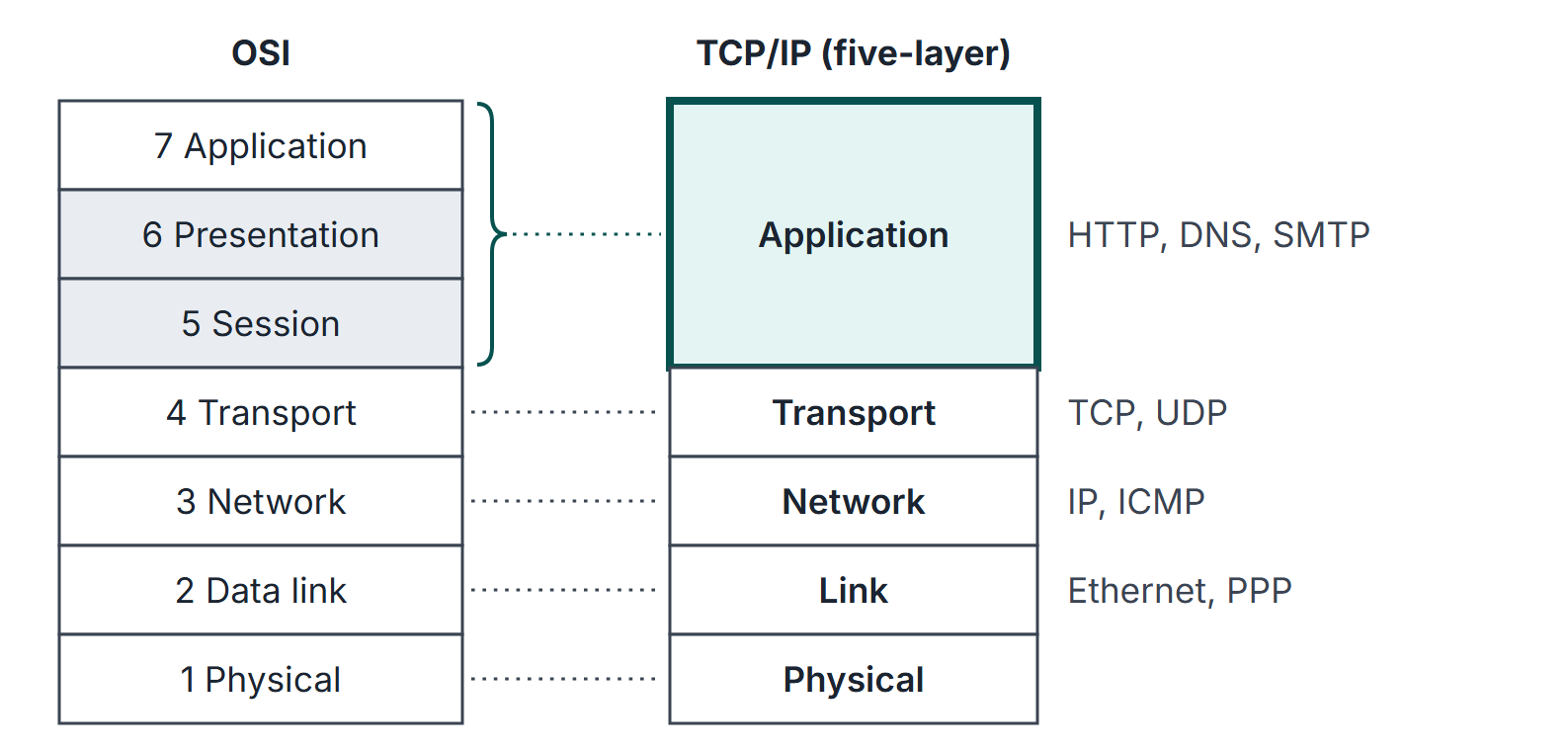
Two reference models organise the vocabulary. The OSI model has seven layers and is the standard way to name functions. The TCP/IP model describes the protocols the Internet actually runs. Both are used to answer "at which layer does X happen" and "which device works at which layer", and layering also explains header-overhead arithmetic.
Prerequisites
None. Binary and hexadecimal notation helps when reading header fields later in the subject.
Core concepts
Vocabulary
| Term | Meaning |
|---|---|
| Layer entity | The software or hardware that implements layer on one machine |
| Peer entities | The two layer- entities on communicating machines; they exchange layer- PDUs |
| Protocol | Rules (formats, order, actions) for messages between peers |
| Service | What layer offers to layer on the same machine |
| Interface | The boundary through which a layer's service is used (service primitives, an API) |
| SDU | Service data unit: the data handed down from the layer above |
| PDU | Protocol data unit: the SDU plus this layer's header (and trailer) |
| Encapsulation | Wrapping the upper PDU as the payload of the lower PDU |
Service versus protocol. A service is vertical (between adjacent layers on one machine); a protocol is horizontal (between peers on different machines). A layer may change its protocol completely without the layer above noticing, as long as the service stays the same.
PDU names in the Internet stack
| Layer | PDU name | Address used | Example protocols |
|---|---|---|---|
| Application | Message | Host name, URL | HTTP, DNS, SMTP, FTP |
| Transport | Segment (TCP), datagram (UDP) | Port number (16 bits) | TCP, UDP |
| Network | Packet or datagram | IP address (32 bits for IPv4) | IP, ICMP |
| Link | Frame | MAC address (48 bits) | Ethernet, PPP, 802.11 |
| Physical | Bit | none | Encoding, signalling |
The OSI reference model
| # | Layer | Main job | Typical association |
|---|---|---|---|
| 7 | Application | Network services for applications | HTTP, DNS, SMTP, FTP |
| 6 | Presentation | Data representation: syntax, encoding, compression, encryption | Format conversion |
| 5 | Session | Dialogue control, synchronisation points (checkpoints) | Session recovery |
| 4 | Transport | Process-to-process delivery, segmentation, end-to-end error and flow control | TCP, UDP, ports |
| 3 | Network | Logical addressing, routing and forwarding across networks, fragmentation | IP, routers |
| 2 | Data link | Framing, physical addressing, error detection, link-level flow control, medium access | Ethernet, switches |
| 1 | Physical | Bits on the medium: voltages, timing, connectors | Hubs, repeaters |
Mnemonic (bottom to top): Physical, Data link, Network, Transport, Session, Presentation, Application. Only layers 1 to 3 run in every router; layers 4 to 7 are end-to-end and run only in hosts.
The TCP/IP model
Tanenbaum describes the TCP/IP model with four layers: link, internet, transport and application. Kurose and Ross teach a five-layer Internet stack: physical, link, network, transport, application. The two are the same idea: the OSI session and presentation layers have no separate place, and their functions (encoding, encryption, session handling) live inside applications or libraries such as TLS.
How it works: encapsulation and demultiplexing
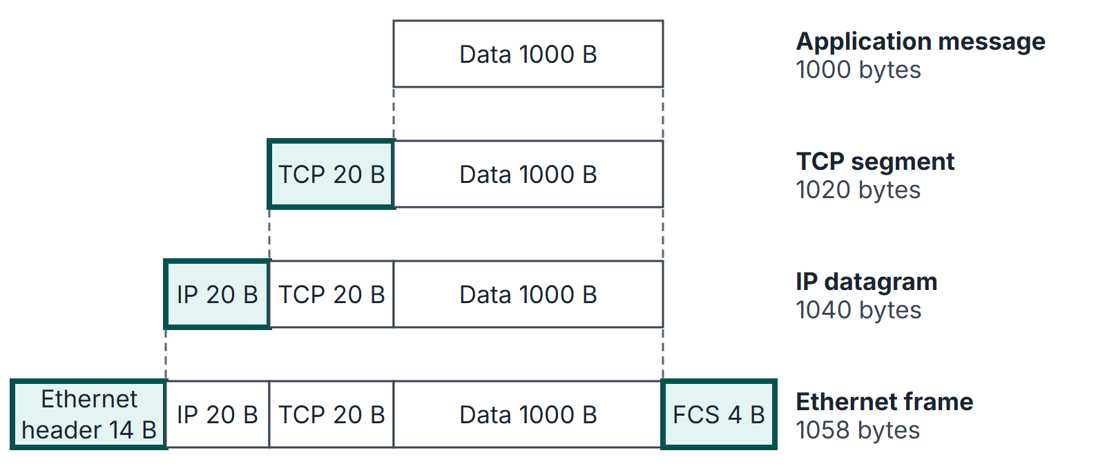
On the sending host, each layer takes the SDU from above, adds its header and passes the result down. On the receiving host, each layer strips its own header, uses a field in that header to decide which upper protocol gets the payload, and passes the payload up. This upward choice is demultiplexing, and every layer has a field for it:
| Layer | Field that names the upper protocol | Values to know |
|---|---|---|
| Link (Ethernet II) | EtherType (16 bits) | IPv4, ARP and IPv6 have distinct values |
| Network (IPv4) | Protocol (8 bits) | ICMP 1, TCP 6, UDP 17, OSPF 89 |
| Transport | Destination port (16 bits) | HTTP 80, HTTPS 443, SMTP 25, FTP control 21, FTP data 20, SSH 22, Telnet 23, DNS 53, DHCP server 67 and client 68 |
A router receiving a frame strips the link header, reads the IP header, decides the next hop, and builds a new frame with new link-layer addresses for the next link. The IP header travels end to end (typically TTL and checksum change; fragmentation also changes length, offset and MF, and may change copied options/IHL); the frame exists only on one link.
Where the awkward protocols sit
| Protocol | Carried in | Usual layer assignment |
|---|---|---|
| ICMP | IP datagram, protocol 1 | Network layer (control companion of IP) |
| ARP | Directly in a link frame (own EtherType) | Glue between network and link layer; often called a link-layer protocol |
| OSPF | Directly in IP, protocol 89 | Network layer (routing control plane) |
| RIP | UDP, port 520 | Application process that maintains network-layer tables |
| BGP | TCP, port 179 | Application process that maintains network-layer tables |
| DHCP | UDP, ports 67 and 68 | Application layer |
| DNS | UDP port 53 (TCP port 53 for large responses and zone transfers) | Application layer |
To decide which layer a protocol belongs to, ask which header the protocol's message is carried in and which layer's job it does. A protocol that rides inside UDP or TCP is an application-layer protocol even if its job is to help the network layer.
Mathematical explanation: header overhead
Let an application message have bytes and let each of layers add bytes of header. The bytes sent are , so the fraction of the transmitted bytes that is header is
and the efficiency (useful fraction) is . The fraction depends on the ratio only, not on the link speed.
When the lower layer has a maximum payload (an MTU), a message larger than the payload is split, and each piece carries the full set of lower headers. With payload limit bytes per frame for the upper data and per-frame overhead , a message of bytes needs frames and bytes in total.
Worked examples
Example 1: fraction of bandwidth spent on headers
A 500-byte message passes down five layers, each adding a 20-byte header. Bytes sent: . Header fraction: . Efficiency .
Example 2: one TCP segment over Ethernet
1000 bytes of data, TCP header 20 bytes (no options), IPv4 header 20 bytes (no options), Ethernet II header 14 bytes (destination MAC 6, source MAC 6, EtherType 2) and FCS 4 bytes. Segment 1020, datagram 1040, frame 1058 bytes (Figure 2). Data fraction of the frame: . If the 8-byte preamble and start delimiter are counted as well, the bytes on the wire are 1066 and the fraction falls to .
Example 3: IP fragmentation to fit a link MTU
A 4000-byte IP payload has to cross a link whose frames carry at most 1480 bytes of IP payload behind a 20-byte IP header (an MTU of 1500). It needs datagrams. The IP header bytes sent are instead of 20. The exact sizes and offsets of IP fragments are in IPv4 Fragmentation.
Example 4: which layers a router touches
A frame from host A to host B crosses two routers. The physical, link and network layers run at both routers; the transport and application headers are read only at A and B. The IP source and destination addresses stay the same on all three links (without NAT); the Ethernet source and destination addresses change on every link.
Important properties and observations
- Hop-by-hop versus end-to-end. Link-layer error detection and retransmission work per link; transport-layer reliability (TCP) works between the two end hosts. A link layer that is reliable on every link still does not give end-to-end reliability: a router may drop or corrupt a packet in its memory.
- Repeated functions. Error detection appears at the link layer (CRC in the frame), the network layer (IPv4 header checksum, header only) and the transport layer (TCP and UDP checksums over a pseudo-header plus data). Flow control appears at the link layer (sliding windows) and at TCP.
- Connection-oriented versus connectionless is a property of a service at a given layer. IP is connectionless and unreliable; TCP builds a connection-oriented, reliable byte stream on top of it; UDP adds only ports and a checksum.
- Devices and layers. Repeater and hub: layer 1, one collision domain. Bridge and switch: layer 2, each port its own collision domain, one broadcast domain. Router: layer 3, separates broadcast domains. Gateways and proxies work at higher layers. Details are in Ethernet, Switches and Bridges.
Common misconceptions.
- "TCP/IP has seven layers." It has four (Tanenbaum) or five (Kurose and Ross); session and presentation are not separate layers.
- "ARP is an application protocol." ARP messages go directly in link-layer frames, not in IP.
- "Routers read port numbers." Plain routers forward on the IP header only. NAT boxes and firewalls do read and rewrite transport headers, which is why NAT is said to violate layering (Network Address Translation).
- "The physical layer handles framing." Framing (finding frame boundaries, bit or byte stuffing) is a data-link function.
GATE examination perspective
- Layer of a function. Routing and logical addressing: network. Framing, MAC addressing, medium access: data link. Process-to-process delivery, ports, end-to-end reliability, congestion control: transport. Encryption, compression, character-code translation: presentation (OSI). Dialogue control and checkpoints: session (OSI).
- Layer of a protocol. Decide by the carrying header (table above). OSPF directly in IP; RIP in UDP; BGP in TCP; DHCP and DNS in UDP.
- Layer of a device. Hub layer 1, switch layer 2, router layer 3. Count collision and broadcast domains from this.
- Overhead arithmetic. ; remember that splitting a message repeats all lower headers in every piece.
- What changes hop by hop. MAC addresses change at every router; IP addresses stay fixed end to end (except through NAT); TTL decreases by one per router and the IPv4 header checksum is recomputed.
Summary
Sources
- A. S. Tanenbaum, D. J. Wetherall, Computer Networks, 5th ed., Pearson, 2011, Section 1.3 (Network Software: 1.3.1 Protocol Hierarchies, 1.3.4 Service Primitives, 1.3.5 The Relationship of Services to Protocols) and Section 1.4 (1.4.1 The OSI Reference Model, 1.4.2 The TCP/IP Reference Model, 1.4.4 A Comparison of the OSI and TCP/IP Reference Models).
- J. F. Kurose, K. W. Ross, Computer Networking: A Top-Down Approach, 8th ed., Pearson, 2021: Section 1.5 (1.5.1 Layered Architecture, 1.5.2 Encapsulation).
- B. A. Forouzan, Data Communications and Networking, 5th ed., McGraw-Hill, 2013: Chapter 2 (Network Models).
- J. Postel, RFC 791, Internet Protocol, 1981, Section 3.1 (protocol field), (consulted 2026-11-11).