
Introduction
Ethernet is the dominant wired local area network technology. Its original form was a shared bus (later a hub) on which all stations contended with CSMA/CD (Medium Access Control). Modern Ethernet is switched: every station has its own full-duplex link to a switch port, so there are no collisions at all, yet the frame format, the 48-bit addresses and the minimum frame size of the classic design have stayed.
The frame format and its size limits, MAC addressing, how a learning switch (bridge) builds its forwarding table, and the difference between hubs, switches and routers in terms of collision domains and broadcast domains are the standard facts. The calculations are frame field sizes, padding, efficiency, address types, switch table traces and domain counts.
Prerequisites
- Medium Access Control: ALOHA, CSMA and CSMA/CD: CSMA/CD, the minimum frame size , binary exponential backoff.
Core concepts
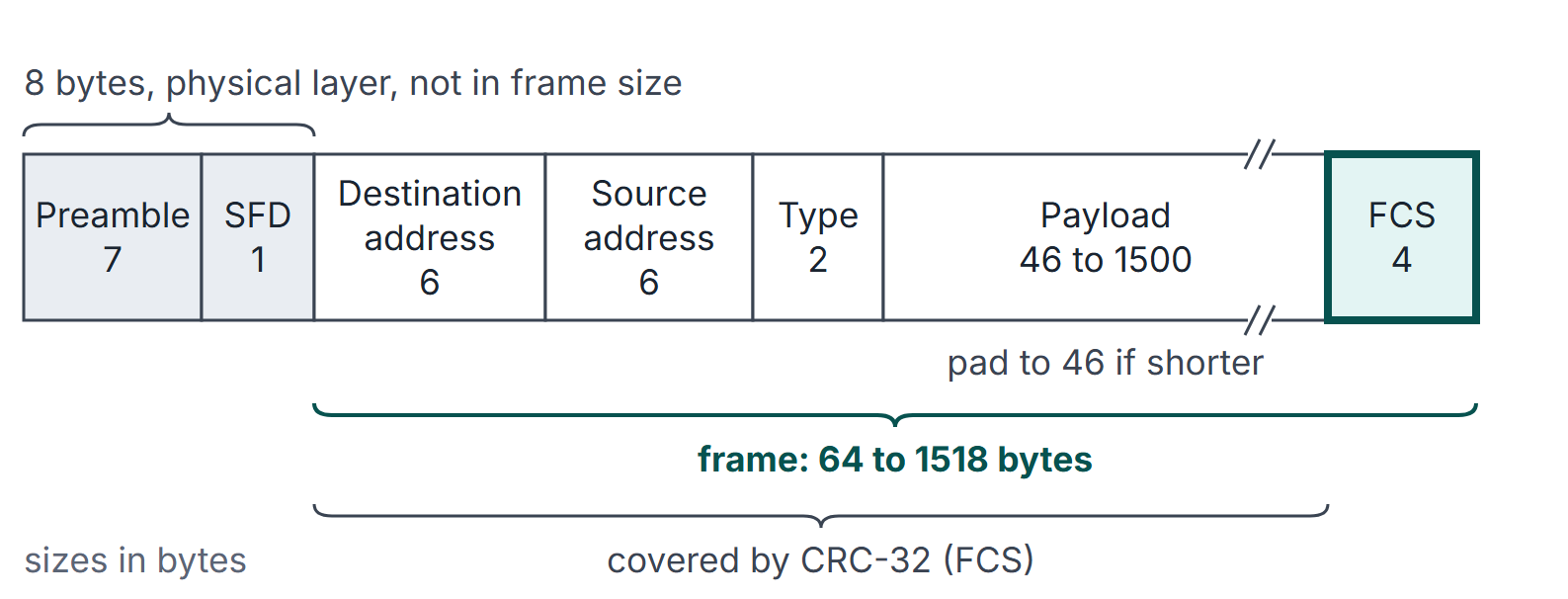
The Ethernet II frame
| Field | Bytes | Purpose |
|---|---|---|
| Preamble | 7 | Alternating 1s and 0s (10101010) to synchronise the receiver's clock |
| Start frame delimiter (SFD) | 1 | 10101011: the frame starts after this byte |
| Destination address | 6 | MAC address of the receiver (or a group or broadcast address) |
| Source address | 6 | MAC address of the sender (always unicast) |
| Type (Ethernet II) or length (802.3) | 2 | Upper-layer protocol, or payload length |
| Payload | 46 to 1500 | Data; padded up to 46 bytes if shorter |
| Frame check sequence (FCS) | 4 | CRC-32 over destination address through payload |
Frame size convention. "Frame size" means destination address through FCS: 64 bytes minimum (), 1518 bytes maximum (). The preamble and SFD (8 bytes) are not counted in the frame size, and neither is the inter-frame gap of 96 bit times (12 bytes) that a sender leaves between frames. On the wire, each frame therefore costs its size plus 20 bytes.
Type or length. A value of at least 1536 (0x0600) in the 2-byte field is a type (IPv4, ARP, IPv6 have distinct values); a value of at most 1500 is a length (IEEE 802.3 framing, with an LLC header in the payload). The values 1501 to 1535 are not used, so a receiver can always tell the two apart.
MAC addresses
A MAC address is 48 bits, written as six hexadecimal bytes such as 3C:52:82:1A:07:F4. The first three bytes are normally the manufacturer's OUI (organisationally unique identifier); the last three are assigned by the manufacturer.
| Address kind | Rule |
|---|---|
| Unicast | Least significant bit of the first byte is 0 |
| Multicast (group) | Least significant bit of the first byte is 1 |
| Broadcast | All 48 bits 1: FF:FF:FF:FF:FF:FF (a special multicast) |
| Locally administered | Second-least significant bit of the first byte is 1 |
Every adapter on the LAN reads the destination address of every frame it sees and passes the frame up only if the address is its own, the broadcast address, or a multicast group it has joined (unless it is in promiscuous mode).
Hubs, bridges, switches and routers
| Device | Layer | Forwards on | Collision domain | Broadcast domain |
|---|---|---|---|---|
| Repeater, hub | 1 | Nothing: repeats every bit to every port | All ports share one | All ports share one |
| Bridge, switch | 2 | Destination MAC address, using a learned table | Each port is its own | All ports share one (broadcasts are flooded) |
| Router | 3 | Destination IP address, using a routing table | Each port is its own | Each port is its own (broadcasts are not forwarded) |
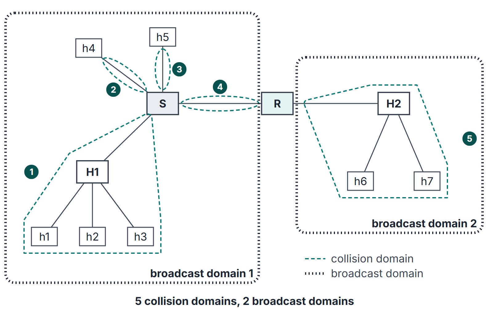
A collision domain is a set of stations whose frames can collide with each other. A broadcast domain is a set of stations reached by a link-layer broadcast. Switches split collision domains; only routers (or VLANs) split broadcast domains.
Algorithms and pseudocode: the learning switch
The switch table maps a MAC address to a port (and a time stamp for ageing). It is filled by self-learning; nobody configures it.
ON-FRAME(f, in_port)
    table[f.src] <- (in_port, now)                // learn or refresh the sender's port
    if f.dst is broadcast or multicast then
        send f on every port except in_port       // flood
    else if f.dst in table then
        p <- table[f.dst].port
        if p = in_port then discard f             // filter: same segment
        else send f on port p                     // forward
    else
        send f on every port except in_port       // flood unknown destination
AGEING: delete entries not refreshed for the ageing time
Each frame performs one forwarding-table lookup and one update: expected table work with ordinary hashing, worst-case work and table storage for learned addresses. Flooding can emit up to copies on a -port switch, so total forwarding work is not always constant. Learning and aging adapt the table as hosts move; an unknown or expired destination is flooded until learned again.
Loops. With redundant links, flooding would circulate frames forever. Bridges run the spanning tree protocol, which disables enough ports to leave a loop-free tree.
Mathematical explanation
Padding. For a payload of bytes, the pad is bytes and the frame is bytes.
Efficiency of one frame on the wire. Counting preamble, SFD and the inter-frame gap, a frame carrying payload bytes occupies bytes of wire time, so
Frame rate. At link rate , back-to-back frames of bytes (frame size) arrive at frames per second.
Domain counting. With hubs , switch ports and router interfaces: every link segment that ends at a switch port or a router interface is its own collision domain (a direct switch-to-router link is one domain); a hub and everything attached to it joins the domain of the port it hangs from; every router interface starts a new broadcast domain.
Worked examples
Example 1: padding
A 20-byte payload needs pad bytes; the frame is 64 bytes and 72 bytes with preamble and SFD. A 1000-byte payload needs no padding; the frame is 1018 bytes. The receiver removes the pad using the length in the upper-layer header (for example the IPv4 total length).
Example 2: efficiency and frame rate
At 100 Mbps, minimum frames (64 bytes, 84 bytes of wire time) arrive at frames per second; maximum frames (1518 bytes, 1538 bytes of wire time) at about 8127 frames per second. Useful throughput with maximum frames: Mbps.
Example 3: address types
First byte 0x3C = 00111100: least significant bit 0, so 3C:52:82:1A:07:F4 is unicast; second bit 0, so it is globally administered. First byte 0x01 (as in 01:00:5E:00:00:FB) has least significant bit 1: multicast. FF:FF:FF:FF:FF:FF is broadcast.
Example 4: a learning switch trace
A switch has hosts A, B, C and D on ports 1, 2, 3 and 4; the table starts empty.
| Frame | Learned | Action |
|---|---|---|
| A to D | A on 1 | D unknown: flood to 2, 3, 4 |
| D to A | D on 4 | A known on 1: forward to 1 only |
| B to A | B on 2 | Forward to 1 |
| C to broadcast | C on 3 | Flood to 1, 2, 4 |
| A to B | (A refreshed) | Forward to 2 |
After five frames the table holds all four hosts, and only the first frame and the broadcast were flooded.
Example 5: counting domains
For the network in Figure 2: on the left of the router, the switch has three ports in use towards hosts and a hub, plus its uplink to the router. Collision domains: the hub segment (three hosts plus the switch port), the two single-host ports, the switch-to-router link, and on the right the hub segment with its two hosts and the router interface: 5 in total. Broadcast domains: one per router interface, 2. Replacing the right hub by a switch would add two collision domains (one per host port) and leave the broadcast domains at 2.
Related material. ARP
Before sending an IP datagram on Ethernet, a host must know the next hop's MAC address. ARP (address resolution protocol) broadcasts "who has IP address X?" in a frame to FF:FF:FF:FF:FF:FF; the owner of X replies by unicast with its MAC address, and both sides cache the mapping. For a destination on another subnet, the host resolves its default router's address, not the final destination's.
Important properties and observations
- Why 64 bytes. The minimum frame comes from for 10 Mbps classic Ethernet (512 bits); switched full-duplex Ethernet keeps it for compatibility.
- Full duplex has no collisions. With a dedicated switch port per host and full duplex, CSMA/CD is not used.
- Switches are transparent. Hosts do not address the switch; it forwards on the destination MAC address it reads.
- Store-and-forward versus cut-through. A store-and-forward switch checks the FCS before forwarding; a cut-through switch starts forwarding after reading the destination address, which lowers latency but forwards damaged frames.
- MAC addresses stay on one link. A router rewrites the source and destination MAC addresses on each hop.
Common misconceptions.
- "A switch separates broadcast domains." Broadcasts are flooded to every port.
- "The preamble is part of the 64-byte minimum." It is not; the 64 bytes run from destination address to FCS.
- "A hub creates a collision domain per port." All its ports share one.
GATE examination perspective
- Field sizes. Addresses 6, type or length 2, payload 46 to 1500, FCS 4; frame 64 to 1518; preamble and SFD 8 extra.
- Padding and efficiency. Pad to 46 payload bytes; include preamble, SFD and gap only when the question says "on the wire".
- Address bits. Unicast or multicast from the least significant bit of the first byte; broadcast is all ones.
- Switch traces. Learn the source first, then forward, flood or filter.
- Domain counts. Hub: one shared domain. Switch: one collision domain per port. Router: one broadcast domain per interface.
Summary
Sources
- A. S. Tanenbaum, D. J. Wetherall, Computer Networks, 5th ed., Pearson, 2011: Section 4.3 (4.3.2 Classic Ethernet MAC Sublayer Protocol, 4.3.4 Switched Ethernet) and Section 4.8 (4.8.2 Learning Bridges, 4.8.3 Spanning Tree Bridges, 4.8.4 Repeaters, Hubs, Bridges, Switches, Routers, and Gateways).
- J. F. Kurose, K. W. Ross, Computer Networking: A Top-Down Approach, 8th ed., Pearson, 2021: Section 6.4 (6.4.1 Link-Layer Addressing and ARP, 6.4.2 Ethernet, 6.4.3 Link-Layer Switches).
- B. A. Forouzan, Data Communications and Networking, 5th ed., McGraw-Hill, 2013: Chapter 13 (Wired LANs: Ethernet) and Chapter 17 (Connecting Devices and Virtual LANs).
- D. C. Plummer, RFC 826, An Ethernet Address Resolution Protocol, 1982, (consulted 2026-11-11).